Addressing Reference
1785 PLC-5
6
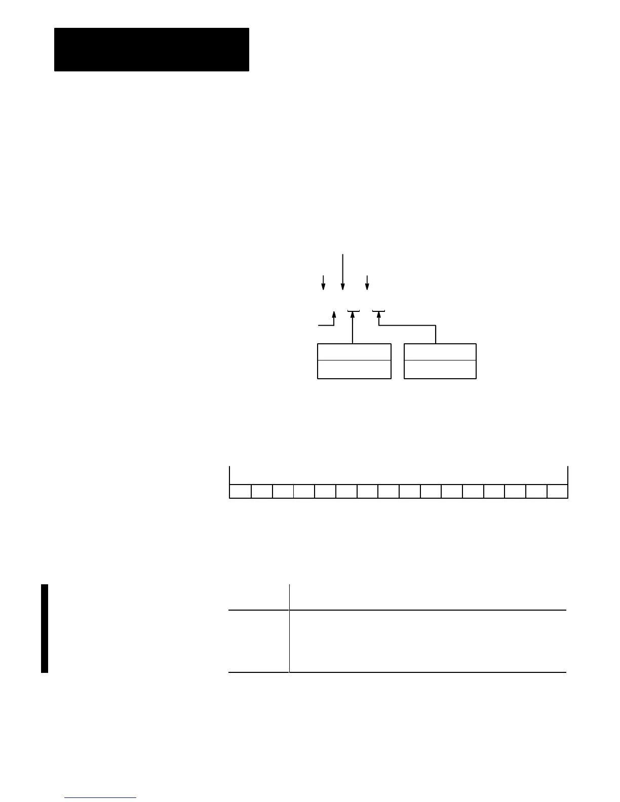
Figure 5 shows how to address the status file of the PLC-5 data table.
Figure 6 shows a word of the status file. Figure 5 shows what is stored in
each word of the status file. For more information, refer to the PLC-5
Programming Software Configuration and Maintenance Manual,
publication 6200-6.4.6.
Figure 5
Logical
Addressing for the Status File
Bit Number
0 – 15 Decimal
W
ord Number
0 – 128 Decimal
Logical
Address Identifier
File Separator
Bit Separator (if addressing a bit)
$ S : 7 / 12
17401–I
Status
file
Identifier
Note:
W
ord number is 0 – 31 on PLC-5/10, -5/12, -5/15, and -5/25 processors.
Figure 6
W
ord of Status file
15 14 13 12 11 10 9 8 7 6 5 4 3 2 1 0
PLC Data Type: signed word (negative values in 2’s complement form)
Range: –32,768 thru +32,767
17411–I
T
able B
Status
File Description
This word of
the status file:
Stores:
S:0 Arithmetic flags
• bit 0 = carry
• bit 1 = overflow
• bit 2 = zero
• bit 3 = sign
Logical Addressing for the
Status File
 Loading...