Addressing Reference
1785 PLC-5
2
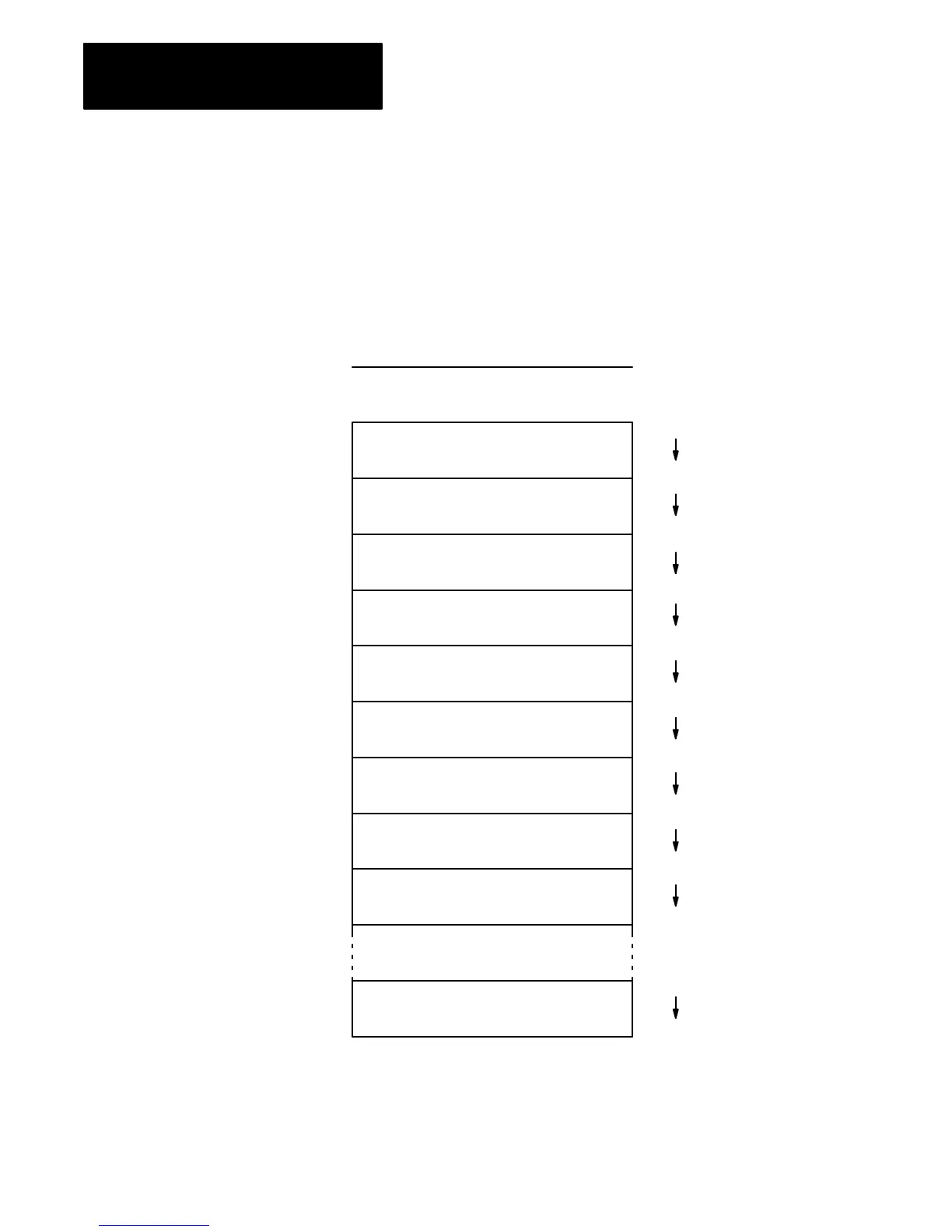
The memory map in Figure 1 shows the logical arrangement of the data
table area of memory in a 1785 PLC-5 processor. This map does not
represent the physical structure of the memory, but it provides the
addressing scheme for the memory in the 1785 PLC-5 data table. The
logical ASCII formats for the memory addresses you can access are shown
in subsequent figures for each section.
Figure 1
Memory
Map of 1785 PLC-5 Processors
17390–I
Output Image
Input Image
Status
Bit (Binary)
Timer
Counter
Control
Integer
Floating-point
Assign File Type as Needed
$O:0
$O:277
$I:0
$I:277
$S:0
$S:128
$B3:0
$B3:999
$T4:0
$T4:999
$C5:0
$C5:999
$R6:0
$R6:999
$N7:0
$N7:999
$F8:0
$F8:999
$_9:0
$_999:999
Memory Map
 Loading...