Addressing Reference
1785 PLC-5
5
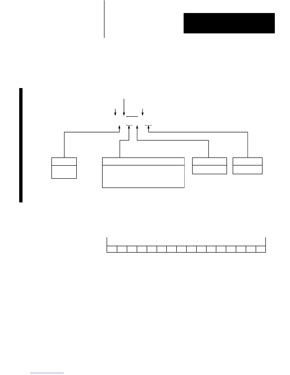
Figure 3
Logical
Addressing for I/O Image T
ables
File
Type
O = Output
I = Input
I/O Rack Number
0 – 3 octal for PLC-5/10, -5/11 -5/12, -5/15,
-5/20
0 – 7 octal for PLC-5/25, -5/30
0 – 17 octal for PLC-5/40, -5/40L
0 – 27 octal for PLC-5/60, -5/60L, -5/80
Bit Number
0 – 17 Octal
I/O Group Number
0 – 7 Octal
Logical
Address Identifier
File Separator
Bit Separator (if addressing a bit)
$ I : 12 3 / 12
17399–I
Word
No.
Figure 4
Word
of Input or Output Image File
17 16 15 14 13 12 11 10 7 6 5 4 3 2 1 0
PLC Data Type: signed word (negative values in 2’s complement form)
Range: –32,768 thru +32,767
17400–I
Logical Addressing for I/O
Image Tables
 Loading...