Addressing Reference
1785 PLC-5
18
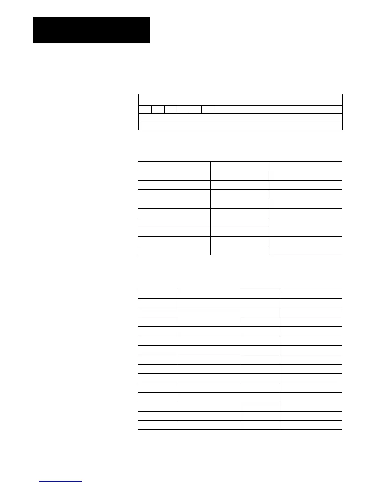
Figure 17
SFC
Status Structure
15 14 13 12 11 10 9 8 7 6 5 4 3 2 1 0
17376–I
SA FS LS Reserved
PRE – Preset V
alue (–32,768 thru +32,767)
TIM –
Active
T
ime (–32,768 thru +32,767)
OV ER DN
T
able J
Example SFC Status Addresses
To Address: PLC Data Type: Example Address:
Whole SFC Status Structure structure $SC9:0
Preset Word signed word $SC9:0.PRE
Active-Time Word signed word $SC9:0.TIM
Scan-active Bit bit $SC9:0.SA
First-scan Bit bit $SC9:0.FS
Last-scan Bit bit $SC9:0.LS
Timer-overflow Bit bit $SC9:0.OV
Step-errored Bit bit $SC9:0.ER
Done Bit bit $SC9:0.DN
T
able K
Block-Transfer
Control Mnemonics
Mnemonic Structure Member Size PLC Data Type
.EN Enable 1 bit bit
.ST Start 1 bit bit
.DN Done 1 bit bit
.ER Error 1 bit bit
.CO Continue 1 bit bit
.EW Enabled Waiting 1 bit bit
.NR No Response 1 bit bit
.TO Time Out 1 bit bit
.RW Read/Write 1 bit bit
.RLEN Requested Word Count 2 bytes signed word
.DLEN Transmitted Word Count 2 bytes signed word
.FILE File-type Number 2 bytes signed word
.ELEM Word Number 2 bytes signed word
.RGS Rack/Group/Slot 2 bytes signed word
 Loading...