Addressing Reference
1785 PLC-5
19
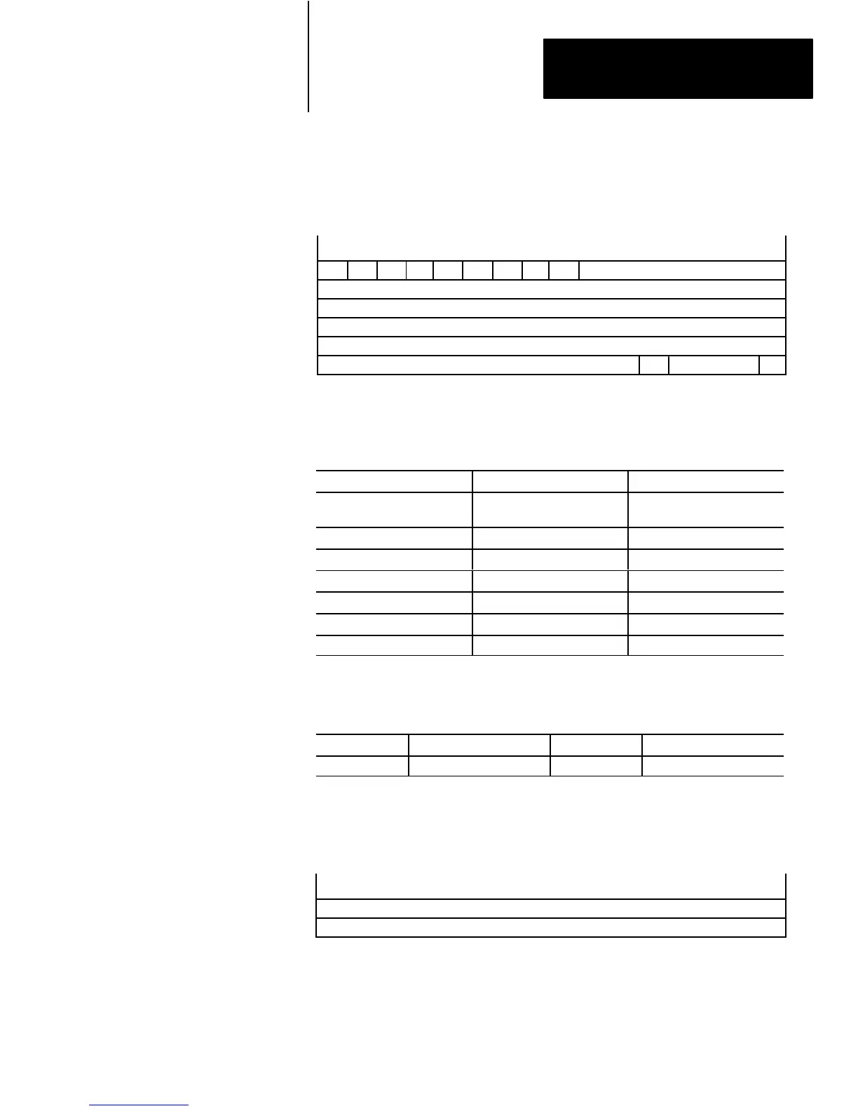
Figure 18
Block-transfer
Control Structure
15 14 13 12 11 10 9 8 7 6 5 4 3 2 1 0
EN ST DN Reserved
RLEN – Requested W
ord Count (–32,768 thru +32,767)
DLEN –
T
ransmitted W
ord Count (–32,768 thru +32,767)
ER CO EW
FILE – File-type Number (–32,768 thru +32,767)
ELEM – W
ord Number (–32,768 thru +32,767)
I/O Rack
NR TO RW
slot
I/O Group
not
used
T
able L
Example Block-transfer Control Addresses
To Address: PLC Data Type: Example Address:
Whole B-T Control
Structure
structure $BT10:0
Requested-word Count signed word $BT10:0.RLEN
Transmitted-word Count signed word $BT10:0.DLEN
File-type Number signed word $BT10:0.FILE
Word Number signed word $BT10:0.ELEM
Rack/Group/Slot signed word $BT10:0.RGS
Done Bit bit $BT10:0.DN
T
able M
ASCII
String Mnemonics
Mnemonic Structure Member Size PLC Data Type
.LEN Length 2 bytes signed word
Figure 19
ASCII
String Structure
1514131211109876543210
LEN – Length specifies an even number of bytes (2 – 82)
A
maximum of 82 bytes of data accessible only by addressing the whole structure.
 Loading...