FLEX I/O Digital Input Modules 13
Publication 1794-IN093E-EN-P - August 2018
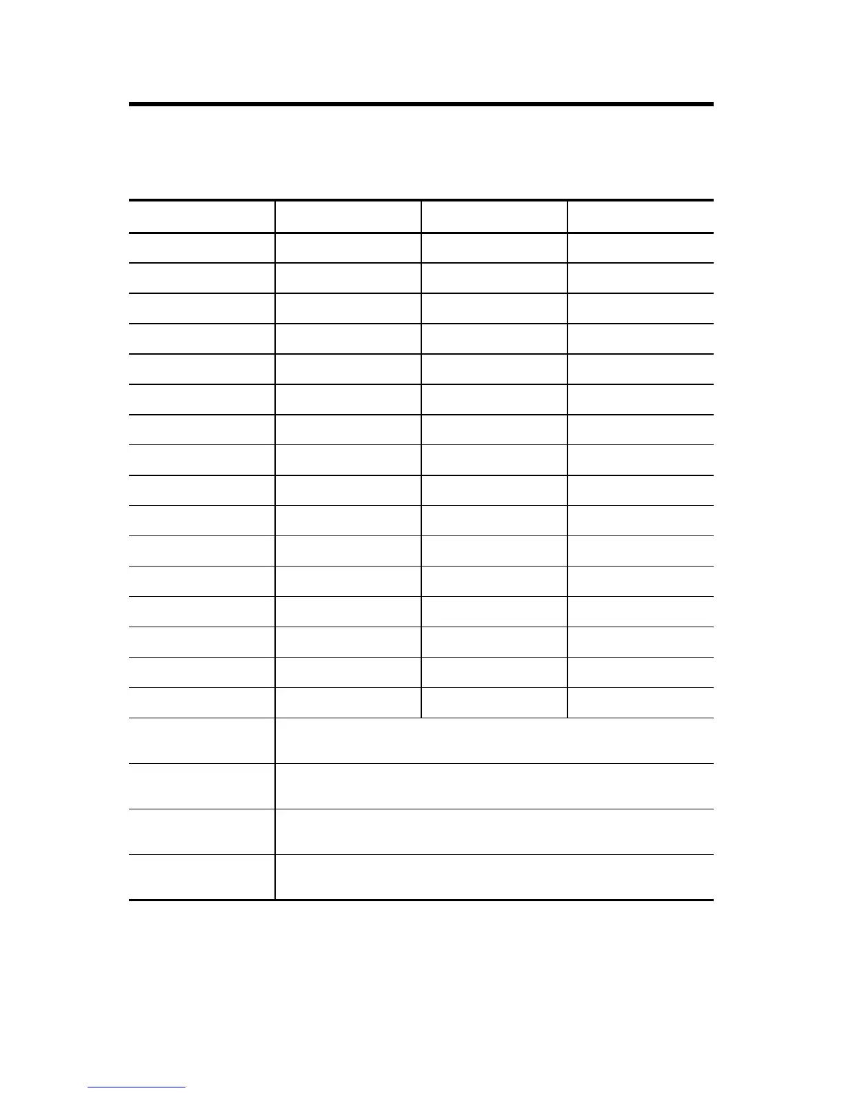
Wiring Connections for 1794-IB32
(use with 1794-TB32 or 1794-TB32S Terminal Base Unit)
Input
(1)
(1)
3-wire devices use signal, return and supply. 2-wire devices use signal and supply
Signal Input Signal
IN 0 A-0 IN 16 B-17
IN 1 A-1 IN 17 B-18
IN 2 A-2 IN 18 B-19
IN 3 A-3 IN 19 B-20
IN 4 A-4 IN 20 B-21
IN 5 A-5 IN 21 B-22
IN 6 A-6 IN 22 B-23
IN 7 A-7 IN 23 B-24
IN 8 A-8 IN 24 B-25
IN 9 A-9 IN 25 B-26
IN 10 A-10 IN 26 B-27
IN 11 A-11 IN 27 B-28
IN 12 A-12 IN 28 B-29
IN 13 A-13 IN 29 B-30
IN 14 A-14 IN 30 B-31
IN 15 A-15 IN 31 B-32
+V1 DC power
(inputs IN0…IN15)
Power terminals 35, 37, 39, and 41 for IN0…IN15.
+V1 connected to terminals 35, 37, 39, and 41.
COM1 DC Return
(inputs IN0…IN15)
Common terminals 36, 38, 40, and 42 for IN0…IN15.
V1 Return connected to terminals 36, 38, 40, and 42.
+V2 DC power
(inputs IN16…IN31)
Power terminals 43, 45, 47, and 49 for IN16…IN31.
+V2 connected to terminals 43, 45, 47, and 49.
COM2 DC Return
(inputs IN16…IN31)
Common terminals 44, 46, 48, and 50 for IN16…IN31.
V2 Return connected to terminals 44, 46, 48, and 50.

 Loading...


