FLEX I/O Digital Input Modules 15
Publication 1794-IN093E-EN-P - August 2018
Set the Input Filter Time
To set the input filter time, set the associated bits in the output image table
(complementary word) for the module.
Read 2 C = Counter Input value of input 15
Write 1 Not used CF CR Input Filter 12...15 Input Filter 0...11
Where
Note:
I = Input
C = Counter value for input 15
CF = Counter fast – where 1 = fast input (raw data), 0 standard input filtered data
CR = Counter reset
C, CR, and CF not available when used with any series 1794-ASB or 1794-ASB2 remote I/O adapter modules.
Image Table Memory Map for the 1794-IB32 Module
Dec 1514131211109876543210
Oct 17161514131211107 6 5 4 3 2 1 0
Read 1 I15I14I13I12I11I10I9I8I7I6I5I4I3I2I1I0
Read 2 I31 I30 I29 I28 I27 I26 I25 I24 I23 I22 I21 I20 I19 I18 I17 I16
Write 1 Not used Input Filter FT
0...31
Not used
Where I = Input status
FT = Input filter time
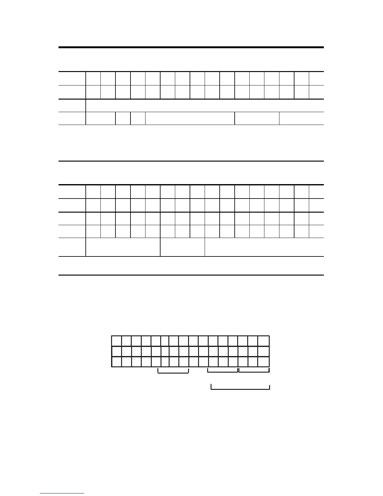
Image Table Memory Map for the 1794-IB16 Module
Dec 1514131211109876543210
Oct 17161514131211107 6 5 4 3 2 1 0
15 14 13 12 11 10 9 8 7 6 5 4 3 2 1 0
FT = 0…7 (1794-IB8)
FT = 0…11 (1794-IB16)
1794-IB16
O:010
Dec.
15 14 13 12 11 10 9 8 7 6 5 4 3 2 1 0
17 16 15 14 13 12 11 10 7 6 5 4 3 2 1 0
Oct.
FT = 12…15
FT = 0…31
1794-IB32

 Loading...


