FLEX I/O DC Input, Output, and Input/Output Analog Modules 9
Publication 1794-IN106D-EN-E - January 2014
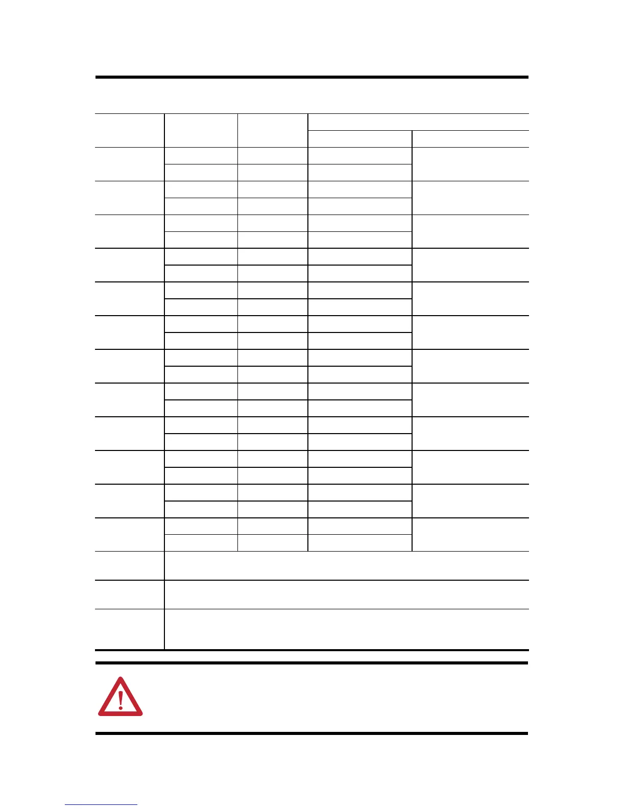
Wire Connections for the 1794-OE12/A Analog Output Module
Channel Signal Type Label
Marking
1794-TB3G or 1794-TB3GS
Output Common Terminal
Output 0 Current I0 A-0 B-17
Voltage V0 A-1
Output 1 Current I1 A-2 B-18
Voltage V1 A-3
Output 2 Current I2 A-4 B-23
Voltage V2 A-5
Output 3 Current I3 A-6 B-24
Voltage V3 A-7
Output 4 Current I4 A-8 B-25
Voltage V4 A-9
Output 5 Current I5 A-10 B-26
Voltage V5 A-11
Output 6 Current I6 A-12 B-31
Voltage V6 A-13
Output 7 Current I7 A-14 B-32
Voltage V7 A-15
Output 8 Current I8 B-19 C-37
Voltage V8 B-20
Output 9 Current I9 B.21 C-39
Voltage V9 B-22
Output 10 Current I10 B-27 C-46
Voltage V10 B-28
Output 11 Current I11 B-29 C-48
Voltage V11 B-30
-V DC
Common
1794-TB3G and 1794-TB3GS – Terminals C-35 and C-51 are internally
connected in the terminal base unit.
+V DC Power 1794-TB3G and 1794-TB3GS – Terminals C-34 and C-50 are internally
connected in the terminal base unit.
Chassis
Ground
(Shield)
1794-TB3G and 1794-TB3GS – Terminals B-16, B-33, C-38, C-40...C-45, and
C-47 are internally connected to chassis ground.
ATTENTION: Use shielded cable for better noise immunity and easier
connection to ground. Connect shield to designated ground points on the
terminal base unit. Ground at the terminal base unit only.

 Loading...


