10 FLEX I/O DC Input, Output, and Input/Output Analog Modules
Publication 1794-IN106D-EN-E - January 2014
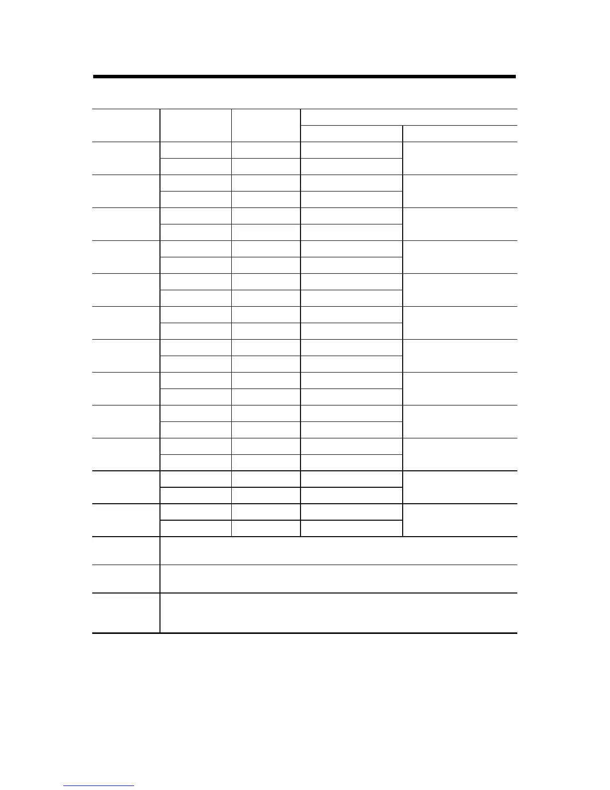
Wire Connections for the 1794-IE8XOE4/A Analog 8 Input/4 Output Module
Channel Signal Type Label
Marking
1794-TB3G or 1794-TB3GS
Output Common Terminal
Output 0 Current I0 A-0 B-17
Voltage V0 A-1
Output 1 Current I1 A-2 B-18
Voltage V1 A-3
Output 2 Current I2 A-4 B-23
Voltage V2 A-5
Output 3 Current I3 A-6 B-24
Voltage V3 A-7
Output 4 Current I4 A-8 B-25
Voltage V4 A-9
Output 5 Current I5 A-10 B-26
Voltage V5 A-11
Output 6 Current I6 A-12 B-31
Voltage V6 A-13
Output 7 Current I7 A-14 B-32
Voltage V7 A-15
Output 8 Current I8 B-19 C-37
Voltage V8 B-20
Output 9 Current I9 B.21 C-39
Voltage V9 B-22
Output 10 Current I10 B-27 C-46
Voltage V10 B-28
Output 11 Current I11 B-29 C-48
Voltage V11 B-30
-V DC
Common
1794-TB3G and 1794-TB3GS – Terminals C-35 and C-51 are internally connected
in the terminal base unit.
+V DC
Power
1794-TB3G and 1794-TB3GS – Terminals C-34 and C-50 are internally connected
in the terminal base unit.
Chassis
Ground
(Shield)
1794-TB3G and 1794-TB3GS – Terminals B-16, B-33, C-38, C-40...C-45, and C-47
are internally connected to chassis ground.

 Loading...


