12 FLEX I/O DC Input, Output, and Input/Output Analog Modules
Publication 1794-IN106D-EN-E - January 2014
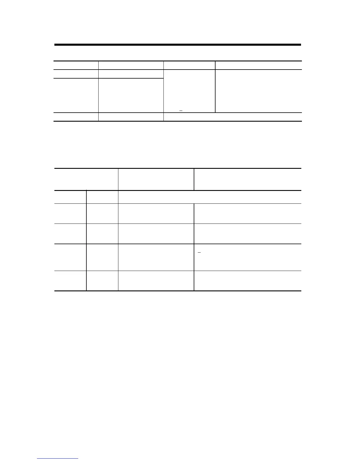
Range Selection Bits for the 1794-IE12, 1794-OE12, and 1794-IE8XOE4
Safe State Selection Bits for the 1794-OE12 and 1794-IE8XOE4
When EN = 0, these bits designate the source of the safe state data for all outputs in
the module.
Range Out of Range Range Setting Cxx
(1)
Channel Configuration
(1)
xx = associated channel pair
-10...+10V DC < -10.0V or > 10.0V Set bits for each
channel pair
00 = off
01 = 0...20 mA
10 = 4...20 mA
11 = +
10V
C01 for channels 0 and 1
C23 for channels 2 and 3
C45 for channels 4 and 5
C67 for channels 6 and 7
C89 for channels 8 and 9
CAB for channels 10 and 11
4...20 mA < 4.0mA or > 20.0 mA
0...20 mA < 0.0 mA or > 20.0 mA
S1/S0 Safe State
Select Source
Safe State Mode Safe State Output Behavior
S1 S0
0 0 Safe State value is in the
output words
Outputs will use Safe State value
0 1 Reserved (Safe State value
is in the output words)
Reserved (Outputs will use Safe State
value)
1 0 Clear/Reset the outputs,
based on range selected
+
10V range – Output set to 0V
4...20 mA range – Output set to 4 mA
0...20 mA range – Output set to 0 mA
1 1 Hold output at its present
level
Outputs will Hold Last State
 Loading...


