FLEX I/O DC Input, Output, and Input/Output Analog Modules 13
Publication 1794-IN106D-EN-E - January 2014
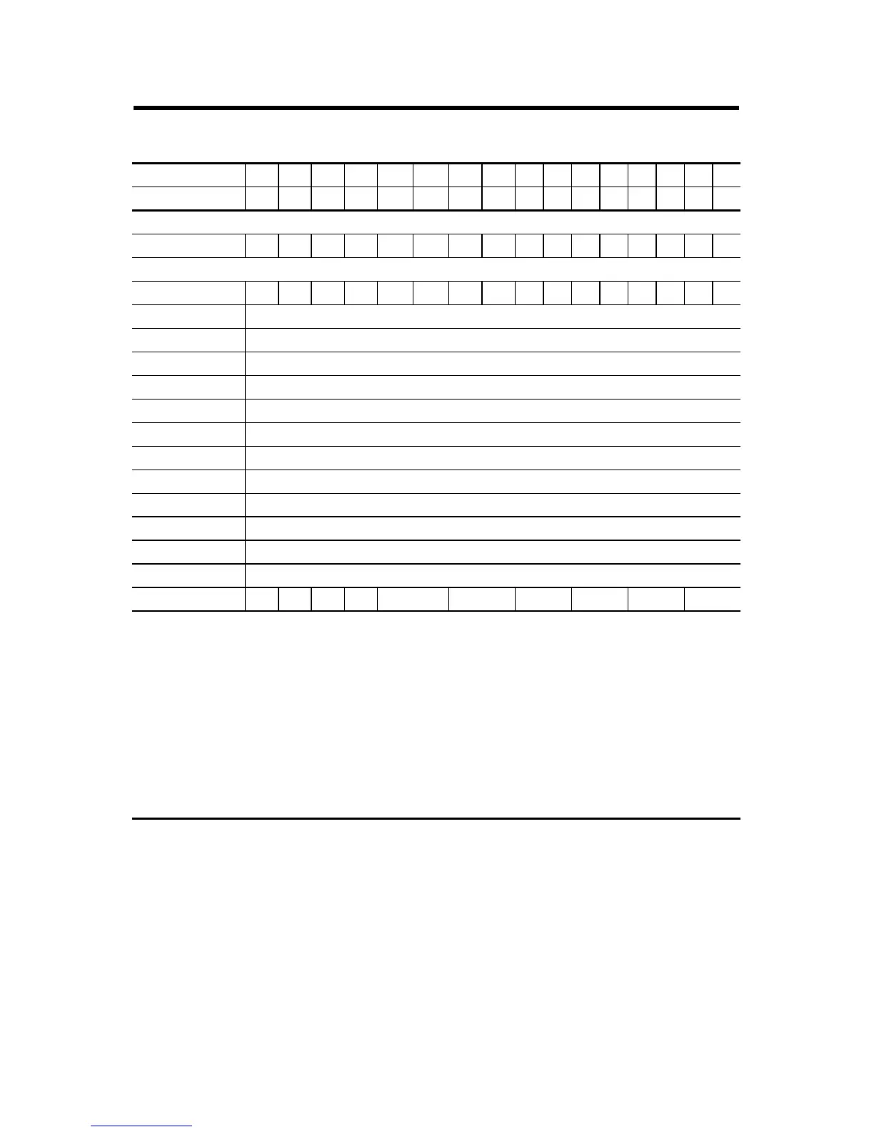
Data Table – 1794-OE12
Dec. 1514131211109 8 76543210
Oct. 171615141312111076543210
Read Words
0 - Status PU FP GF NU W11 W10 W9 W8 W7 W6 W5 W4 W3 W2 W1 W0
Write Words
0 - Reserved ENS1S0WR0 0 0 0 00000000
1 - Output 0 Signed 2’s Complement data Value of Channel 0
2 - Output 1 Signed 2’s Complement data Value of Channel 1
3 - Output 2 Signed 2’s Complement data Value of Channel 2
4 - Output 3 Signed 2’s Complement data Value of Channel 3
5 - Output 4 Signed 2’s Complement data Value of Channel 4
6 - Output 5 Signed 2’s Complement data Value of Channel 5
7 - Output 6 Signed 2’s Complement data Value of Channel 6
8 - Output 7 Signed 2’s Complement data Value of Channel 7
9 - Output 8 Signed 2’s Complement data Value of Channel 8
10 - Output 9 Signed 2’s Complement data Value of Channel 9
11 - Output 10 Signed 2’s Complement data Value of Channel 10
12 - Output 11 Signed 2’s Complement data Value of Channel 11
13 - Configuration 0 0 0 0 CAB C89 C67 C45 C23 C01
Where:
PU = Power up bit
FP = Field power fault
GF = General fault
NU = Not used
Wx = Wire off (x = associated channel)
EN = Enable outputs
S1/S0 = Safe state source – When EN = 0, these bits indicate source of safe state output.
WR = Wire-off reset
Cxx = Configuration
 Loading...


