14 Rockwell Automation Publication 2080-UM004C-EN-E - March 2015
Chapter 2 Install and Wire Your Module
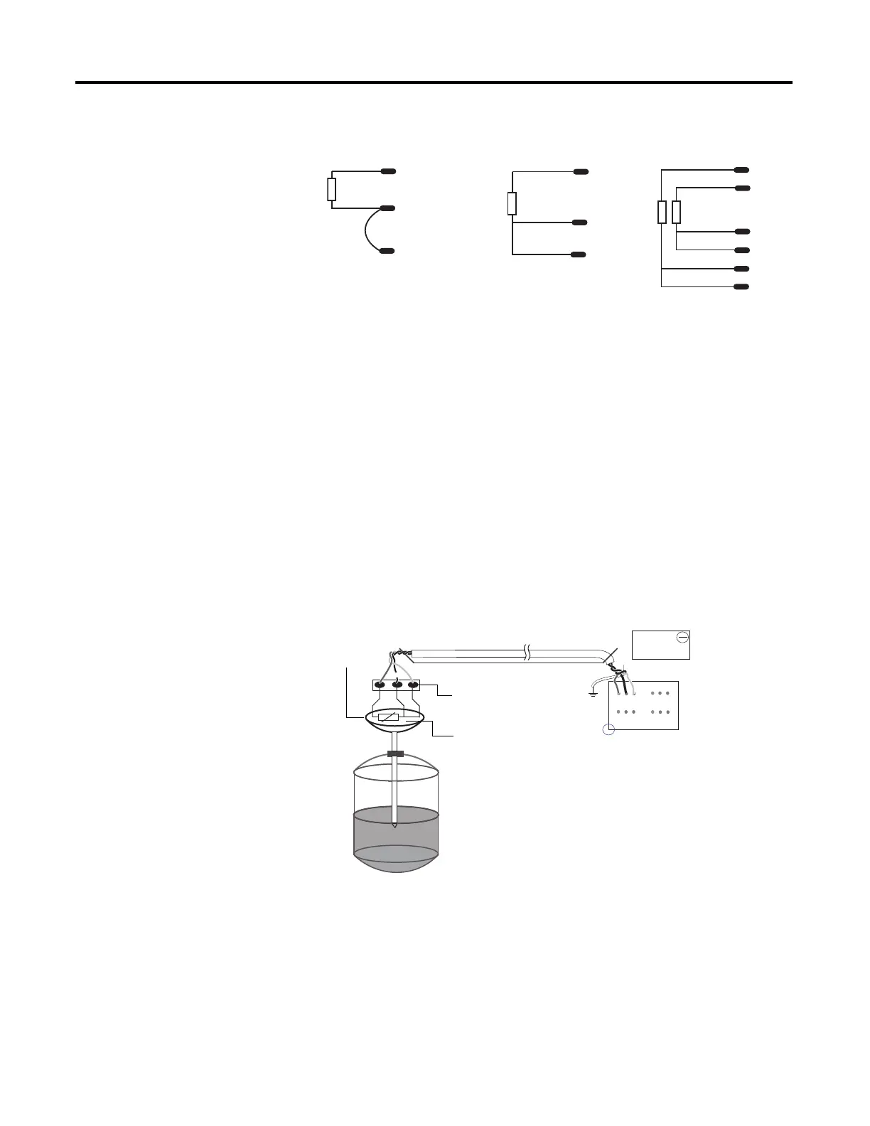
Wire the Sensors
For better accuracy in noisy industrial environments, 3- or 4-wire RTD sensors
are mostly used. While using these sensors, the resistance added by lead lengths is
compensated by an additional third wire in case of 3-wire RTD and two
additional wires, in bridge configuration, in case of 4-wire RTD. For 2-wire RTD
sensor in this module, this lead compensation is provided by using an external
50 mm 22 AWG shorting wire between terminals A2, A3 and B2, B3 for channel
0 and 1, respectively. Shielded twisted pair cables are to be utilized for remote use
of these sensors with cable shield grounded at controller end.
Wire the RTD Module and RTD Sensor in the Field
The RTD sensing element should always be connected between terminals B1(+)
and B2(-) for channel 1, and A1(+) and A2(-) for channel 0 in the module.
Terminals B3 and A3 should always be shorted to B2 and A2, respectively, to
complete the constant current loop. Mismatch in wiring can cause erroneous,
over, or underrange readings.
white
red
Ch0+
Ch0-
Ch0L
white
red
red
green
black
black
white
red
red
Ch1+
Ch1-
Ch1L
Ch0-
Ch0L
Ch0+
Ch0-
Ch0L
Ch0+
2-wire sensor
connection
3-wire single
sensor connection
3-wire dual
sensor connection
45778
NOTE: This illustration provides for channel 0 only for 2- and 3-
wire single sensor connections. The wire colors illustrate a
particular type of RTD sensor available in market.
1
2
3
1 2 3 4 5 6
1 2 3 4 5 6
2080-RTD2
B
A
Red
Green
Black
Blue
Red
Blue
Black
Process
temperature
Measurement
Shielded twisted wire cable
Field screw
junction box
3-wire
RTD
Oil filled
thermowell
45779
3-wire RTD shown
Cable tray/conduit
 Loading...
