Allen-Bradley, Rockwell Automation, and Rockwell Software are trademarks of Rockwell Automation, Inc. Trademarks not belonging to Rockwell Automation are property of their respective companies.
Rockwell Otomasyon Ticaret A.Ş., Kar Plaza İş Merkezi E Blok Kat:6 34752 İçerenköy, İstanbul, Tel: +90 (216) 5698400
Rockwell Automation maintains current product environmental information on its website at
http://www.rockwellautomation.com/rockwellautomation/about-us/sustainability-ethics/product-environmental-compliance.page
.
Publication 802T-IN004A-EN-P - September 2002 PN–462117
Copyright © 2002 Rockwell Automation, Inc. All rights reserved. Printed in the U.S.A.
After wiring has been completed, check that all wires are in the wiring
cavity of the terminal block so they will not interfere with the switch
when it is plugged into the terminal block.
Recheck all wiring terminal screws for tightness.
Note: For switches that have been factory wired, check wire color and
their position in the terminal block for proper circuit hookup.
• Grounding of switch should be achieved per National Electric
Code (NFPA 70) requirements. Grounding terminal is located in
the terminal block housing.
• Arrange control wiring according to terminal markings.
• Tighten terminal screws according to specifications.
• Only use insulated connectors.
Actuator Head Positioning
The actuator head may be placed in any of four positions on the switch
body. Loosen the four captive screws. Place the head in the desired
position and securely re-tighten the four screws (see figure below).
Lever Positioning
The lever on rotary actuated devices is adjustable to any position
through 360° around the shaft. Loosen the nut, move
the lever to the
desired position and securely re-tighten the nut (see figure below).
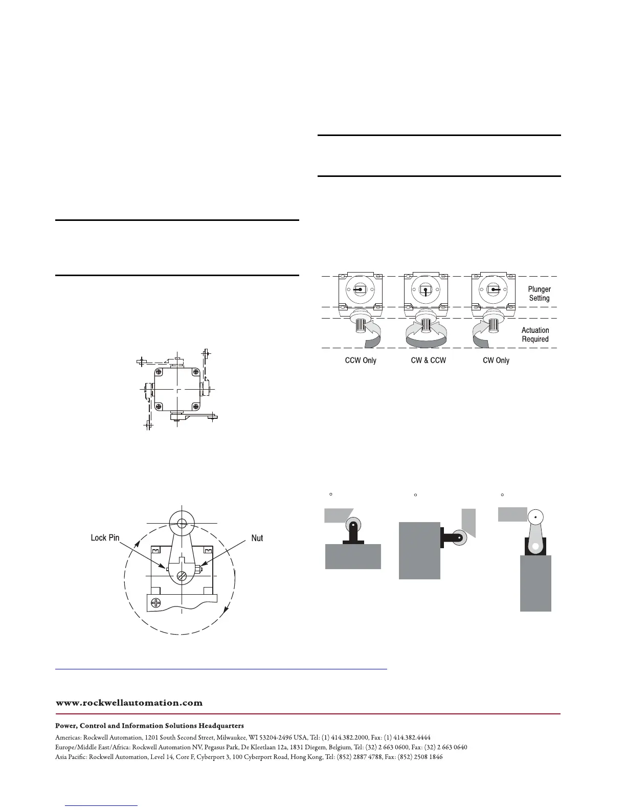
Changing Direction of Actuation
The switch action of lever operated limit switches may be adjusted to
operate in either a clockwise, a counterclockwise, or both directions
movement of the shaft.
To change the actuation direction, follow the steps below:
Step 1: Loosen the four head mounting screws and remove the
operating head from the switch body.
Step 2: Locate the plunger on the underside of the operating head.
Step 3: Pull the plunger outward and rotate it in steps of 90 ° to
provide the operating mode desired. The respective settings are shown
in the figure below.
Step 4: Make sure the plunger is pushed back inward and the “O” ring
is properly seated before the operating head is reattached to the switch
body.
Step 5: Securely re-tighten the operating head mounting screws.
Step 6: Check for the desired actuation mode.
Methods of Actuation Examples
IMPORTANT Pay close attention to the terminal numbering on the
terminal block when wiring this switch. Terminals 1 and 2 or
5 and 6 are normally open contacts.
Terminals 3 and 4 or 7 and 8 are normally closed contacts.
IMPORTANT This procedure must be performed in a clean environment to
avoid the introduction of foreign material into the operating
mechanism.
802T–APD
802T–W1A 1.5 in. long
90
Non-overtravel Dog
802T–DPD
Top Push Roller
30 Non-overtravel Dog
802T–KPD
Side Push Roller
30 Non-overtravel Dog
Vmax = 30 ft/min @ actuator
F max = 150 cycles/min
 Loading...