10 Rockwell Automation Publication 1794-IN082D-EN-P - January 2019
FLEX I/O EtherNet/IP Adapters
7. Connect the adapter wiring as shown under Connecting Wiring later in
this document.
Mount on a Panel or Wall
If mounting this adapter to a panel or wall, refer to publication 1794-IN135,
Panel Mounting Kit, Cat. No. 1794-NM1/B.
Mount or Replace the Adapter on an Existing System
1. Remove the Ethernet plug-in connector from the bottom of the adapter.
2. Disconnect any adapter wiring jumpered to the adjacent terminal base.
3. Disconnect any user power wiring connections to the adapter.
4. Using a screwdriver or similar tool, open the module locking mechanism
and remove the module from the base unit to which the adapter will
be attached.
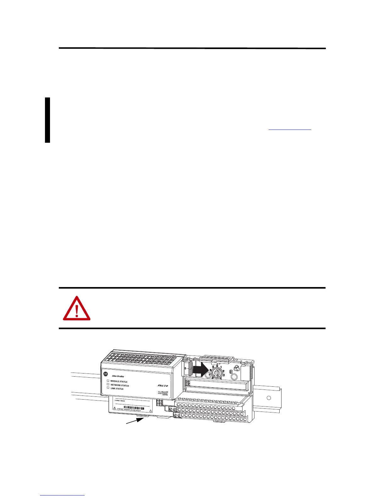
5. Push the Flexbus connector toward the right side of the terminal base to
unplug the backplane connection.
6. Release the DIN rail locking tab (C) and remove the adapter.
ATTENTION: Make certain the Flexbus connector is completely clear of the
adapter. The slide must be completely to the right and the raised spot on the
slide visible.
Locking Tab C
Terminal base of I/O
module adjacent to
the 1794-AENT
adapter.
31244CC

 Loading...


