10 Rockwell Automation Publication 5069-IN013D-EN-P - April 2018
CompactLogix 5380 Controllers
4. Connect the DC(—) wire from the external SA DC power
supply to the first SA(—) terminal.
5. Connect a wire from an Earth Ground location to the first
Ground ( )
on the RTB. The Earth Ground location can
be the external SA power supply, the DIN rail, or other Earth
Ground location.
Connect SA AC Power
Before you connect an external DC power source to the SA power
RTB, make sure that the SA power source is adequately sized.
1. Verify that the SA power source is not powered on.
2. Strip insulation from the wires that you connect to the RTB.
3. Connect the L1/AC(+) wire from the external SA AC power
source to the first SA(+) terminal.
4. Connect the L2/N/AC(—) wire from the external SA AC
power source to the first SA(—) terminal.
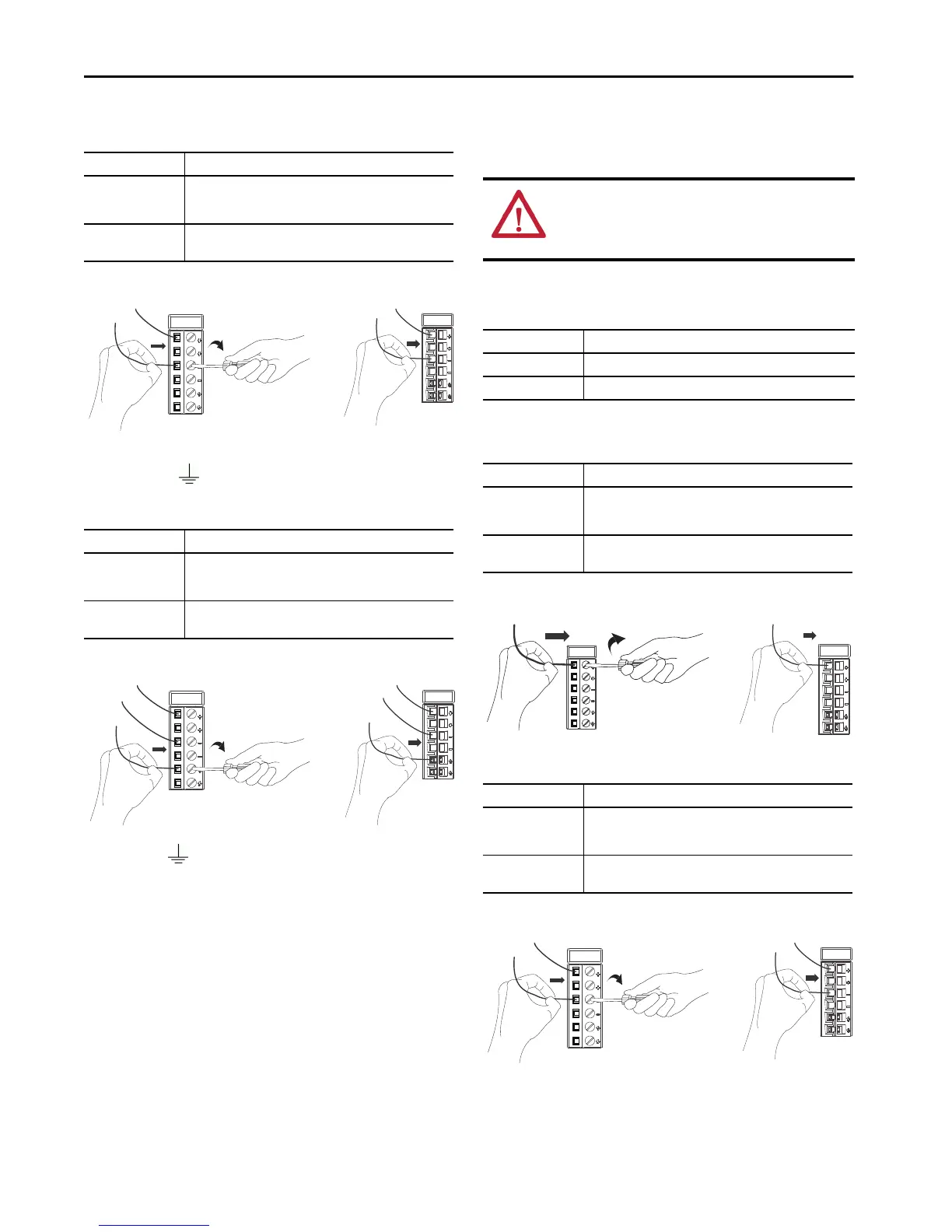
RTB Type Action
Screw
1. Insert the wire into the terminal.
2. Turn the screwdriver to close the terminal on the wire. Torque the
screw to 0.4 N•m (3.5 lb•in).
Spring
Push the wire into the terminal.
If necessary, you can crimp a wire ferrule on the wire and insert it.
RTB Type Action
Screw
1. Insert the wire into the terminal.
2. Turn the screwdriver to close the terminal on the wire. Torque the
screw to 0.4 N•m (3.5 lb•in).
Spring
Push the wire into the terminal.
If necessary, you can crimp a wire ferrule on the wire and insert it.
TIP
This symbol denotes an Earth Ground terminal that provides a low
impedance path between electrical circuits and earth for functional
purposes and provides noise immunity improvement. This connection
must be made for functional purposes.
5069-RTB6-SPRING RTB5069-RTB6-SCREW RTB
5069-RTB6-SPRING RTB5069-RTB6-SCREW RTB
WARNING: If you connect or disconnect wiring while the field-
side power is on, an electrical arc can occur. This could cause an
explosion in hazardous location installations. Be sure that power is
removed or the area is nonhazardous before proceeding.
RTB Type Action
Screw Strip12 mm (0.47 in) of insulation from the wires.
Spring Strip 10 mm (0.39 in) of insulation from the wires.
RTB Type Action
Screw
1. Insert the wire into the terminal.
2. Turn the screwdriver to close the terminal on the wire. Torque the
screw to 0.4 N•m (3.5 lb•in).
Spring
Push the wire into the terminal.
If necessary, you can crimp a wire ferrule on the wire and insert it.
RTB Type Action
Screw
1. Insert the wire into the terminal.
2. Turn the screwdriver to close the terminal on the wire. Torque the
screw to 0.4 N•m (3.5 lb•in).
Spring
Push the wire into the terminal.
If necessary, you can crimp a wire ferrule on the wire and insert it.
5069-RTB6-SPRING RTB5069-RTB6-SCREW RTB
5069-RTB6-SPRING RTB5069-RTB6-SCREW RTB

 Loading...


