Rockwell Automation Publication 5069-IN013D-EN-P - April 2018 11
CompactLogix 5380 Controllers
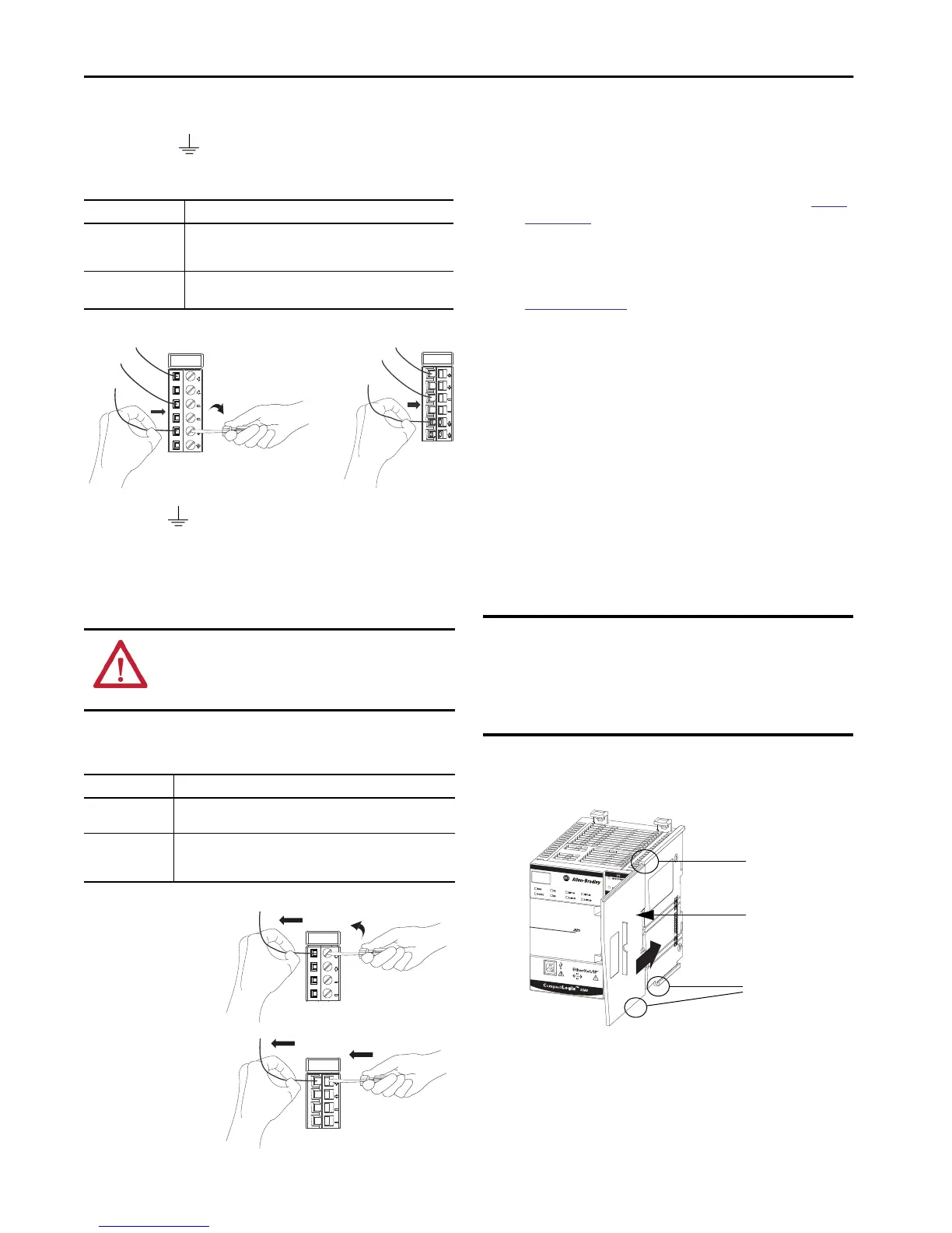
5. Connect a wire from an Earth Ground location to the first
Ground ( ) on the RTB. The Earth Ground location can
be the external SA power supply, the DIN rail, or other Earth
Ground location.
Disconnect Wires from the RTBs
If necessary, complete the following tasks to disconnect wires from any
RTB on the controller.
Install Compact 5000 I/O Modules
Complete one of the following:
• If you do not need to install Compact 5000 I/O modules
before you turn on power to the controller, proceed to
Install
the End Cap.
• If you must install Compact 5000 I/O modules to the system
before you turn on power to the controller, install the modules
beginning on the right side of the controller. Then proceed to
Install the End Cap.
For more information on how to install Compact 5000 I/O
modules, see the installation instructions available with each
Compact 5000 I/O module catalog number.
Install the End Cap
A 5069-ECR end cap ships with the controller.
You must install an end cap on the right side of the last module in a
CompactLogix 5380 system. The end cap covers the exposed
interconnections on the last module in the system. If you do not install
the end cap before powering the system, equipment damage or injury
from electric shock can result.
If the end cap is not installed and you have installed all required
modules in the system, install the end cap as described in this section.
1. Align the end cap with interlocking pieces on the controller.
2. Push the end cap toward the DIN rail until it locks into place.
RTB Type Action
Screw
1. Insert the wire into the terminal.
2. Turn the screwdriver to close the terminal on the wire. Torque the
screw to 0.4 N•m (3.5 lb•in).
Spring
Push the wire into the terminal.
If necessary, you can crimp a wire ferrule on the wire and insert it.
TIP
This symbol denotes an Earth Ground terminal that provides a low
impedance path between electrical circuits and earth for functional
purposes and provides noise immunity improvement. This connection
must be made for functional purposes.
WARNING: If you connect or disconnect wiring while the field-
side power is on, an electrical arc can occur. This could cause an
explosion in hazardous location installations. Be sure that power is
removed or the area is nonhazardous before proceeding.
RTB Type Action
Screw
1. Turn the screwdriver counter-clockwise to open the terminal.
2. Remove the wire.
Spring
1. Insert and hold a screwdriver in the right-side terminal.
2. Remove the wire.
3. Pull out the screwdriver.
5069-RTB6-SPRING RTB5069-RTB6-SCREW RTB
5069-RTB6-SPRING RTB
5069-RTB6-SCREW RTB
IMPORTANT You install the end cap after the last module is installed on
the DIN rail. This design helps to prevent the end cap from
going beyond the locked position.
If you push the end cap beyond the locked position or insert it
from the backwards direction, you can damage the MOD
power bus and SA power bus connector.
Top Interlocking
Pieces
End Cap
Bottom Interlocking
Pieces

 Loading...


