Rockwell Automation Publication 5069-IN013D-EN-P - April 2018 5
CompactLogix 5380 Controllers
About the Controller
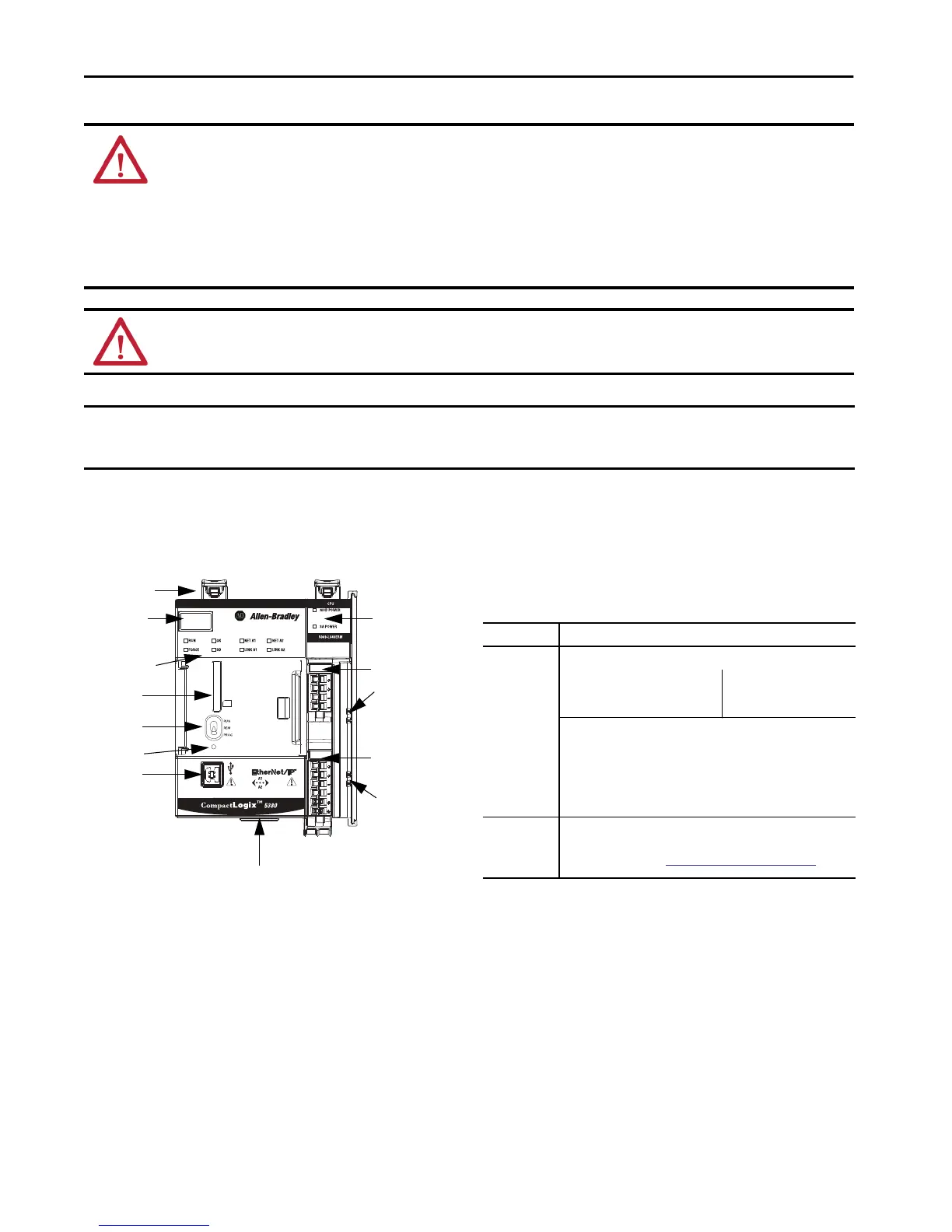
The following graphic shows a CompactLogix 5380 controller.
Required System Components
Before you install the controller, verify that you have the
following components.
WARNING:
• If you connect or disconnect wiring while the field-side power is on, an electrical arc can occur. This could cause an explosion in hazardous location
installations. Be sure that power is removed or the area is nonhazardous before proceeding.
• When you insert or remove the SD memory card while power is on, an electrical arc can occur. This could cause an explosion in hazardous location
installations. Be sure that power is removed or the area is nonhazardous before proceeding.
• When you press the reset button while power is on, an electrical arc can occur. This could cause an explosion in hazardous location installations. Be sure that
power is removed or the area is nonhazardous before proceeding.
• When you change switch settings while power is on, an electrical arc can occur. This could cause an explosion in hazardous location installations. Be sure that
power is removed or the area is nonhazardous before proceeding.
WARNING: Do not use the USB port in hazardous locations.
IMPORTANT
Any illustrations, charts, sample programs, and layout examples that are shown in this publication are intended solely for the purposes of example. Since
there are many variables and requirements that are associated with any particular installation, Rockwell Automation does not assume responsibility or
liability for actual use that is based upon the examples that are shown in this publication.
SA Power MOD Power
DIN Rail Latches
Status Indicators
SD Card Slot
Reset Button
Mode Switch
Four-character
Display
Ethernet ports (bottom of controller)
Module Power and
Sensor/Actuator
Power Status
Indicators
MOD Power RTB
SA Power RTB
USB Port
MOD Power Bus
Connector
SA Power Bus
Connector
Components Needed to Install a CompactLogix 5380 Controller
Component Description
Removable
Terminal Blocks
(RTB)
One of the following RTB types for each power type:
MOD Power (system-side power)
• 5069-RTB4-SCREW RTB
• 5069-RTB4-SPRING RTB
SA Power (field-side power)
• 5069-RTB6-SCREW RTB
• 5069-RTB6-SPRING RTB
IMPORTANT: RTBs do not ship with CompactLogix 5380 controllers. You
must order RTBs separately.
The RTBs are available in 5069 RTB kits. The 5069-RTB64-SCREW kit
contains the 5069-RTB6-SCREW and 5069-RTB4-SCREW RTBs. The 5069-
RTB64-SPRING kit contains the 5069-RTB6-SPRING and 5069-RTB4-SPRING
RTBs. We recommend that you order only the RTB type that your system
requires.
External power
supply for
Module (MOD)
Power
A power supply that is adequately sized to provide MOD power, that is,
system-side power, to the CompactLogix 5380 system.
For more information, see
System Power Considerations on page 7.

 Loading...


