6 Rockwell Automation Publication 5069-IN013D-EN-P - April 2018
CompactLogix 5380 Controllers
System Planning
Follow these rules when planning your system configuration:
• You must mount the DIN rail horizontally.
Rockwell Automation does not support a CompactLogix 5380
system that is installed vertically.
• The controller is the left-most component in the system.
• Local Compact 5000 I/O modules are installed to the right of
the controller.
The number of local I/O modules that are supported varies by
controller catalog number.
• Before power-up, make sure that the end cap is installed on the
rightmost Compact 5000 I/O module in the system.
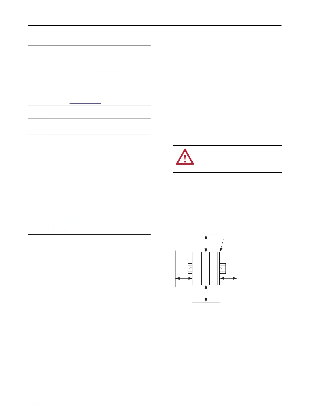
Spacing
Maintain spacing from enclosure walls, wireways, and adjacent
equipment.
The minimum distance on all sides of the CompactLogix 5380 system
varies based on the operating temperature, as follows:
• 50.80 mm (2.00 in.) at 55 °C (131 °F)
• 101.66 mm (4.00 in) at 60 °C (140 °F)
External power
supply for
Sensor/
Actuator (SA)
Power
A power supply that is adequately sized to provide SA power, that is, field-
side power, to the CompactLogix 5380 system.
For more information, see
System Power Considerations on page 7.
Tools
You use the following tools to wire the RTBs:
• Screwdriver
• Wire stripper
• Wires
For more information on available wire sizes and wire insulation stripping
length, see
Specifications on page 14.
DIN rail
Compatible zinc-plated, chromate steel DIN rail.
You can use the EN50022 - 35 x 7.5 mm (1.38 x 0.30 in.) DIN rail.
EtherNet/IP
network
components
If your CompactLogix 5380 controller operates on an EtherNet/IP network,
you must install the network and all required components.
Software
You can use the following software with your controller:
• BOOTP DHCP EtherNet/IP Commissioning Tool - We recommend that you
use version 3.02.00 or later.
• Logix Designer application:
– Version 28.00.00 or later - 5069-L320ER, 5069-L340ERM
– Version 29.00.00 or later - 5069-L306ER, 5069-L306ERM, 5069-
L310ER, 5069-L310ER-NSE, 5069-L310ERM, 5069-L320ERM, 5069-
L330ER, 5069-L330ERM, 5069-L340ER
– Version 30.00.00 or later - 5069-L350ERM, 5069-L380ERM,
5069-L3100ERM
• RSLinx® Classic software - Minimum version is based on the version of
Logix Designer application that you use with the controller.
– Version 3.80.00 or later with Logix Designer application, version 28
– Version 3.81.00 or later with Logix Designer application, version
29.00.00 or later
When you install the controller, you use one of these software tools to
assign an IP address to the controller. For more information, see
Set the
Network Internet Protocol (IP) Addresses on page 12.
For more information on how to use software after the controller is
installed, see the publications that are listed in Additional Resources on
page 15.
Components Needed to Install a CompactLogix 5380 Controller
Component Description
ATTENTION: Do not discard the end cap. Use this end cap
to cover the exposed interconnections on the last module
on the DIN rail. Failure to do so could result in equipment
damage or injury from electric shock.
Top
Bottom
SideSide
5380 Controller
Compact 5000 I/O
End cap
Compact 5000 I/O

 Loading...


