Rockwell Automation Publication 5069-IN013D-EN-P - April 2018 7
CompactLogix 5380 Controllers
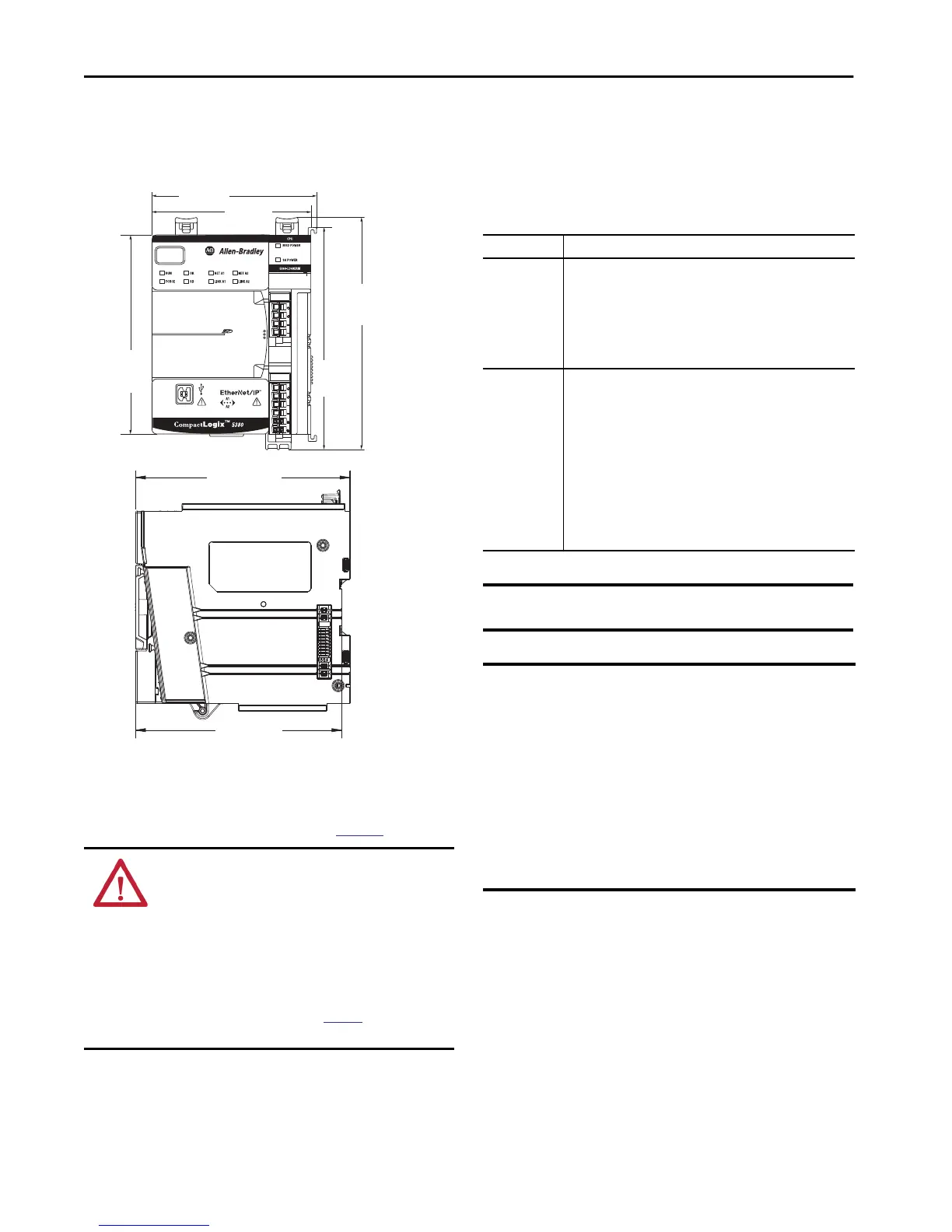
Dimensions
The controller dimensions are as follows.
Ground Considerations
You must ground DIN rails according to the Industrial Automation
Wiring and Grounding Guidelines, publication
1770-4.1
You can use the EN50022 - 35 x 7.5 mm (1.38 x 0.30 in.) DIN rail.
System Power Considerations
The CompactLogix 5380 controller provides power to a
CompactLogix 5380 system via RTBs that are connected to external
power supplies and installed on the controller.
The RTBs provide the following power to the system.
ATTENTION: This product is grounded through the DIN rail to
chassis ground. Use zinc-plated chromate-passivated steel DIN
rail to assure proper grounding. The use of other DIN rail
materials (for example, aluminum or plastic) that can corrode,
oxidize, or are poor conductors, can result in improper or
intermittent grounding. Secure DIN rail to mounting surface
approximately every 200 mm (7.8 in.) and use end-anchors
appropriately. Be sure to ground the DIN rail properly. Refer to
Industrial Automation Wiring and Grounding Guidelines,
Rockwell Automation publication
1770-4.1 for more
information.
SA Power MOD Power
98.10 mm
(3.86 in.)
137.84 mm
(5.43 in.)
123.00 mm
(4.84 in.)
143.97 mm
(5.67 in.)
136.81 mm
(5.39 in.)
130.31 mm
(5.13 in.)
101.66 mm
(4.00 in.)
Power Type Description
MOD Power
System-side power that is used to operate the CompactLogix 5380
system. MOD power is provided through the MOD power RTB and passed
across the MOD power bus.
• The total continuous current draw across the MOD power bus must not
be more than 10 A, max, at 18...32V DC.
• Confirm that the external MOD power supply is adequately sized for
the total MOD power bus current draw in the system, plus the MOD
power inrush current requirements.
SA Power
Field-side power that is used to power field-side devices. SA power is
provided through the SA power RTB and passed across the SA power bus.
• If you are using DC voltage for SA power, the total continuous current
draw across the SA power bus must not be more than 10 A, max
at 18…32V DC.
• If you are using AC voltage for SA power, the total continuous current
draw across the SA power bus must not be more than 10 A, max
at 18…240V AC.
• You can use a 5069-FPD field potential distributor to establish
additional SA power buses in a CompactLogix 5380 system.
• Confirm that the external SA power supply is sized adequately for the
total SA power current draw in the system, including the combined
inrush current requirements for all connected modules.
IMPORTANT CompactLogix 5380 controllers do not have an embedded
power supply that powers the system.
IMPORTANT You can connect power from one external power supply to the
MOD power and SA power connects. However, we strongly
recommend that you use separate external power supplies
for MOD power and SA power respectively.
The practice of using separate external power supplies can help to
prevent unintended consequences that can result if you use one
supply.
If you use separate external power supplies, the loss of power from
one external power supply does not affect the availability of
power from the other supply. For example, if separate external
power supplies are used and SA power is lost, MOD power remains
available for the Compact 5000 I/O modules.
 Loading...


