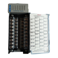
ControlLogix DC (10-30V) Sourcing Input Module 7
Publication 1756-IN006A-EN-P - December 2000
Wire the Module
You can only connect wiring to your module through an RTB or IFM.
The example below shows how to wire the module.
After completing field-side wiring, secure the wires in the strain relief
area with a cable-tie.
1756-IV16
12
34
5
6
7
8
910
11
12
1314
1516
1718
19
20
1. All terminals with the same name are connected together on the module. For example, DC
(+) can be connected to either terminal marked DC-1+. If you are daisy chain wiring from
one of these terminals to other RTBs, only connect wiring to one terminal.
2. When you daisy chain from a group to another RTB, always connect the daisy chain to the
terminal directly connected to the supply wire, as shown above.
3. This wiring example shows a single voltage source.
4. If separate power sources are used, do not exceed the specified isolation voltage.
–+
Daisy chain to other RTBs
Group 0Group 0
Group 1Group 1
DC COM
42552
IN-0
IN-2
IN-4
IN-6
DC-0 +
IN-8
IN-10
IN-12
IN-14
DC-1 +
IN-1
IN-3
IN-5
IN-7
DC-0 +
IN-9
IN-11
IN-13
IN-15
DC-1 +
NOTES:
Allen-Bradley Motors

 Loading...


