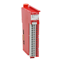
Do you have a question about the Allen-Bradley 5069-IF8 and is the answer not in the manual?
Identifies the different models of 5069 Compact I/O analog I/O modules available.
Details on building a 5069 Compact I/O system and its configuration requirements.
Explains how input and output data is exchanged between modules and controllers.
Describes the purpose and application of the 5069-ARM and 5069-FPD modules.
Details restrictions on module operations based on its operating mode.
Covers rolling timestamps, floating point data format, and module accuracy.
Explains data quality indicators, fault, and status reporting mechanisms.
Details module inhibiting, electronic keying, and alarm latching capabilities.
Describes how to scale module data and discusses module accuracy specifications.
Details the 5069-IF8 module's channels and supported input types.
Explains the function and settings of Notch and Digital Filters.
Covers underrange/overrange detection and process/rate alarms.
Details the 5069-IY4 module's channels and supported input types.
Covers filters, sensor types, and offsets for signal conditioning.
Discusses underrange/overrange, alarms, and cold junction compensation.
Details the 5069-OF4/OF8 modules' channels and available output ranges.
Explains output clamping limits and output ramping/rate limiting.
Covers connection fault handling, status indicators, and protection features.
Steps for creating a project and adding modules using Logix Designer.
Details on General, Connection, and Module Info categories for configuration.
Specific configuration parameters for module channels.
Pre-calibration steps and differences between input/output module calibration.
Step-by-step guide for calibrating analog input modules.
Explains the meaning of module status indicators (MOD and I/O).
Methods for using Logix Designer to identify and resolve module faults.
Explains how module tags are named and how to access them.
Lists and defines configuration and input tags for the 5069-IF8 module.
| Manufacturer | Allen-Bradley |
|---|---|
| Number of Inputs | 8 |
| Input Type | Voltage/Current |
| Resolution | 16-bit |
| Category | I/O Module |
| Module Type | Analog Input |
| Voltage Input Range | ±10V, 0-10V, 1-5V, 0-5V |
| Current Input Range | 0...20mA, 4...20mA |
| Enclosure Type Rating | None (open-style) |
| Operating Temperature | 0°C to 55°C (32°F to 131°F) |
| Relative Humidity | 5% to 95% (non-condensing) |
| Module Location | Chassis |


