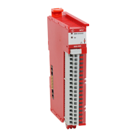
Do you have a question about the Allen-Bradley 5069-OF4 and is the answer not in the manual?
| Brand | Allen-Bradley |
|---|---|
| Model | 5069-OF4 |
| Category | I/O Systems |
| Language | English |
Provides essential safety, installation, and operational guidelines for the 5000 series analog I/O modules.
Describes creating a Logix Designer project and transferring configuration data to modules.
Details how modules indicate data quality using Fault and Uncertain tags.
Describes how fault and status data is reported via Logix Designer and status indicators.
Covers configuring modules to return data in signal or engineering units using two points.
Explains the Notch Filter's function for noise removal and lists available frequency settings for the 5069-IY4.
Covers detection of signals outside input ranges and lists thresholds for 5069-IY4 module.
Describes detecting disconnected wires for various modes and the resulting module behavior.
Defines output behavior and duration settings when a connection fault occurs.
Limits output to a configured range, even when controller commands outside the range.
Prevents damage from driving current exceeding channel limits and turns output off.
Details using Discover Modules or New Module options to add modules to a Logix Designer project.
Explains how Logix Designer indicates faults via I/O configuration tree and Module Properties.


