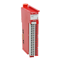
Do you have a question about the Allen-Bradley 5069-OA16 and is the answer not in the manual?
Details compatibility requirements between Logix 5000 controllers and Compact 5000 I/O modules.
Covers methods to secure access to controllers, adapters, and I/O modules by authorized users.
Details the steps required to construct a system using Compact 5000 I/O modules, locally or remotely.
Explains the different power types (System-side and Field-side) required for the modules.
Guides on creating Logix Designer projects and transferring configuration data to modules.
Highlights additional awareness items for Compact 5000 I/O safety modules, including certification.
Explains how modules indicate channel data quality, representing accuracy via module input tags.
Describes how the control system uses CIP Sync timestamping by using the IEEE 1588 protocol.
Details how to increase time for input point transitions to improve noise immunity.
Explains how timestamping registers a time reference to a change in input data using CIP Sync.
Monitors for the loss of field power on an SA power bus, detecting faults when power is lost.
Detects when a wire is disconnected or a load is missing for each output point in the Off state.
Helps prevent output damage by detecting conditions with more current than the output can handle.
Prevents output damage by detecting excessive temperature from high current loads.
Configures module behavior when a connection fault occurs between owner-controller and output module.
Details how to schedule times for module outputs to turn On or Off using the MAOC instruction.
Describes features available on Compact 5000 I/O safety input modules, including suitability levels.
Details features available on Compact 5000 I/O safety output modules, including suitability levels.
Explains how safety modules report fault and status data via module tags monitored in Logix Designer.
Describes creating new local or remote Compact 5000 I/O safety modules in Logix Designer.
Explains common configuration categories for safety modules: General, Connection, Safety, Module Info.
Explains how to set the RPI rate and configure Connection Reaction Time Limit for safety modules.
Provides steps and considerations for replacing a safety module on a CIP Safety network.
Explains how to manually set the Safety Network Number (SNN) for integrity on initial download.
Covers conditions and actions for replacing a Compact 5000 I/O safety module in a Logix 5000 system.
Describes the Module (MOD) Status indicator on Compact 5000 I/O digital modules.
Shows the status indicators on the Compact 5000 I/O safety input module.
Illustrates the status indicators on the Compact 5000 I/O safety output module.
Explains how Logix Designer application indicates fault conditions via warning signals and status information.
Describes conditions that can trigger an InternalFault on a safety output module.
Details the tags associated with 5069-IB8S and 5069-IB8SK safety input modules.
Describes the tags associated with 5069-OBV8S and 5069-OBV8SK safety output modules.
Provides wiring diagrams for 5069-IB8S/IB8SK safety input modules suitable for Category 3 applications.
Shows wiring diagrams for 5069-OBV8S/OBV8SK safety output modules in Bipolar and Sourcing modes.
Lists calculated safety data (PFD, PFH, MTTF) for 5069-IB8S and 5069-IB8SK safety input modules.
Provides calculated safety data (PFD, PFH, MTTF) for 5069-OBV8S and 5069-OBV8SK safety output modules.
| Manufacturer | Allen-Bradley |
|---|---|
| Product Type | Digital Output Module |
| Number of Outputs | 16 |
| Output Type | Sourcing |
| Voltage Category | 24V DC |
| Output Current per Channel | 0.5A |
| Total Output Current | 8A |
| Module Location | Local |
| Series | 5069 |
| Module Type | Output |
| Operating Voltage | 20.4 to 26.4V DC |
| Isolation Voltage | 250V AC |
| Backplane Current Consumption | 120mA at 5V DC, 60mA at 24V DC |


 Loading...