EasyManuals Logo

Allen-Bradley micrologix 1500 Installation Instructions

Allen-Bradley micrologix 1500
122 pages
To Next Page IconTo Next Page
To Previous Page IconTo Previous Page
Page #11 background imageLoading...
Page #11 background image
MicroLogix™ 1500 Programmable Controller Base Units 11
Publication 1764-IN001A-ML-P
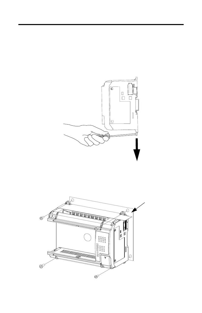
To remove your base unit from the DIN rail:
1. Place a flat-blade screwdriver in the DIN rail latch at the bottom of the base
unit.
2. Holding the base unit, pry downward on the latch until the latch locks in the
open position. This releases the base unit from the DIN rail.
Using Mounting Screws
Mount to panel using #8 or M4 screws.
Mounting Template
Allen-Bradley Parts

Other manuals for Allen-Bradley micrologix 1500

Questions and Answers:

Question and Answer IconNeed help?

Do you have a question about the Allen-Bradley micrologix 1500 and is the answer not in the manual?

Allen-Bradley micrologix 1500 Specifications

General IconGeneral
Processor Type16-bit
Programming LanguageLadder Logic
MountingDIN rail or panel mount
Programming SoftwareRSLogix 500
Communication PortsRS-232
Power Supply24V DC
Operating Temperature0°C to 55°C (32°F to 131°F)
Controller TypeProgrammable Logic Controller (PLC)

Related product manuals