EasyManuals Logo

Allen-Bradley micrologix 1500 Installation Instructions

Allen-Bradley micrologix 1500
122 pages
To Next Page IconTo Next Page
To Previous Page IconTo Previous Page
Page #6 background imageLoading...
Page #6 background image
6 MicroLogix™ 1500 Programmable Controller Base Units
Publication 1764-IN001A-ML-P
Base Unit Description
Table 2 Standard Base Units
Catalog Number Base Unit I/O and Power Supply
1764-24AWA 120V ac inputs/ relay outputs/ 120/240V ac power supply
1764-24BWA 24V dc inputs/ relay outputs/ 120/240V ac power supply
1764-28BXB 24V dc inputs/ FET and relay outputs/ 24V dc power supply
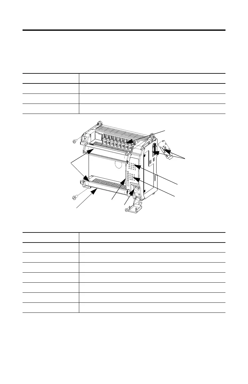
Table 3 Base Unit Description
Feature Description
1 Removable Terminal Blocks
2 Interface to Expansion I/O, Removable ESD Sticker
3 Input LEDs
4 Output LEDs
5 RS-232 Communication Port (CH0)
6 Status LEDs
7 Terminal Doors and Label
2
3
4
5
6
7
1
1

Other manuals for Allen-Bradley micrologix 1500

Questions and Answers:

Question and Answer IconNeed help?

Do you have a question about the Allen-Bradley micrologix 1500 and is the answer not in the manual?

Allen-Bradley micrologix 1500 Specifications

General IconGeneral
Processor Type16-bit
Programming LanguageLadder Logic
MountingDIN rail or panel mount
Programming SoftwareRSLogix 500
Communication PortsRS-232
Power Supply24V DC
Operating Temperature0°C to 55°C (32°F to 131°F)
Controller TypeProgrammable Logic Controller (PLC)

Related product manuals