12 MicroLogix™ 1500 Programmable Controller Base Units
Publication 1764-IN001A-ML-P
To install your base unit using mounting screws:
1. Remove the mounting template from the inside back cover of this document.
2. Secure the template to the mounting surface. (Make sure your base unit is
spaced properly, see “Controller Spacing” on page 9).
3. Drill holes through the template.
4. Remove the mounting template.
5. Mount the base unit.
6. Leave the protective debris strips attached until you are finished wiring the
base unit and any other devices.
Wiring the Controller
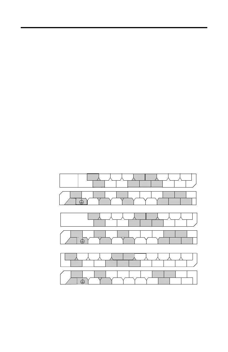
Terminal Block Layout
1764-24AWA
1764-28BXB
1764-24BWA
+24V
DC
COM 0
I / 1
I / 0
I / 3
I / 2
I / 4
DC
COM 1
I / 6
I / 5
DC
COM 2
I / 7
I / 9
I / 8
I / 11
I / 10
DC
POWER
OUT
24BWA
COM
VAC
VDC 0
85-265
VAC
O / 5
VAC
VDC 1
VAC
VDC 2
VAC
VDC 4
O / 7 O / 8
O / 10
O / 4O / 1O / 0 O / 2 O / 6 O / 9 O / 11
VAC
VDC 5
24BWA
VAC
VDC 3
O / 3
L2
AC
COM 0
I / 1
I / 0
I / 3
I / 2
I / 4
AC
COM 1
I / 6
I / 5
AC
COM 2
I / 7
I / 9
I / 8
I / 11
I / 10
24AWA
NOT
USED
NOT
USED
85-265
VAC
O / 5
VAC
VDC 0
L2
VAC
VDC 1
VAC
VDC 2
VAC
VDC 4
O / 7 O / 8 O / 10
O / 4
O / 1
O / 0
L1
O / 2 O / 6 O / 9 O / 11
VAC
VDC 5
24AWA
VAC
VDC 3
O / 3
I / 4 I / 6
I / 5
I / 9
I / 8 I / 10
I / 15
28BXB
NOT
USED
NOT
USED
DC
COM 0
I / 0
I / 1 I / 3
I / 2
DC
COM 1
I / 7
DC
COM 2
I / 12 I / 14
I / 13I / 11
24 VDC
O / 7
VAC
VDC 0
COM
VAC
VDC 1
VAC
VDC 3
O / 9 O / 10
O / 6O / 1O / 0 O / 2 O / 11
28BXB
O / 4
VDC 2 O / 5O / 3
VDC
COM 2
O / 8
VAC
VDC 4
+24V
L1

 Loading...


