MicroLogix™ 1500 Programmable Controller Base Units 13
Publication 1764-IN001A-ML-P
Wire Requirements
Wiring torque = 1.13 Nm (10 in-lb) rated; 1.3 Nm (12 in-lb) maximum
Wiring Recommendation
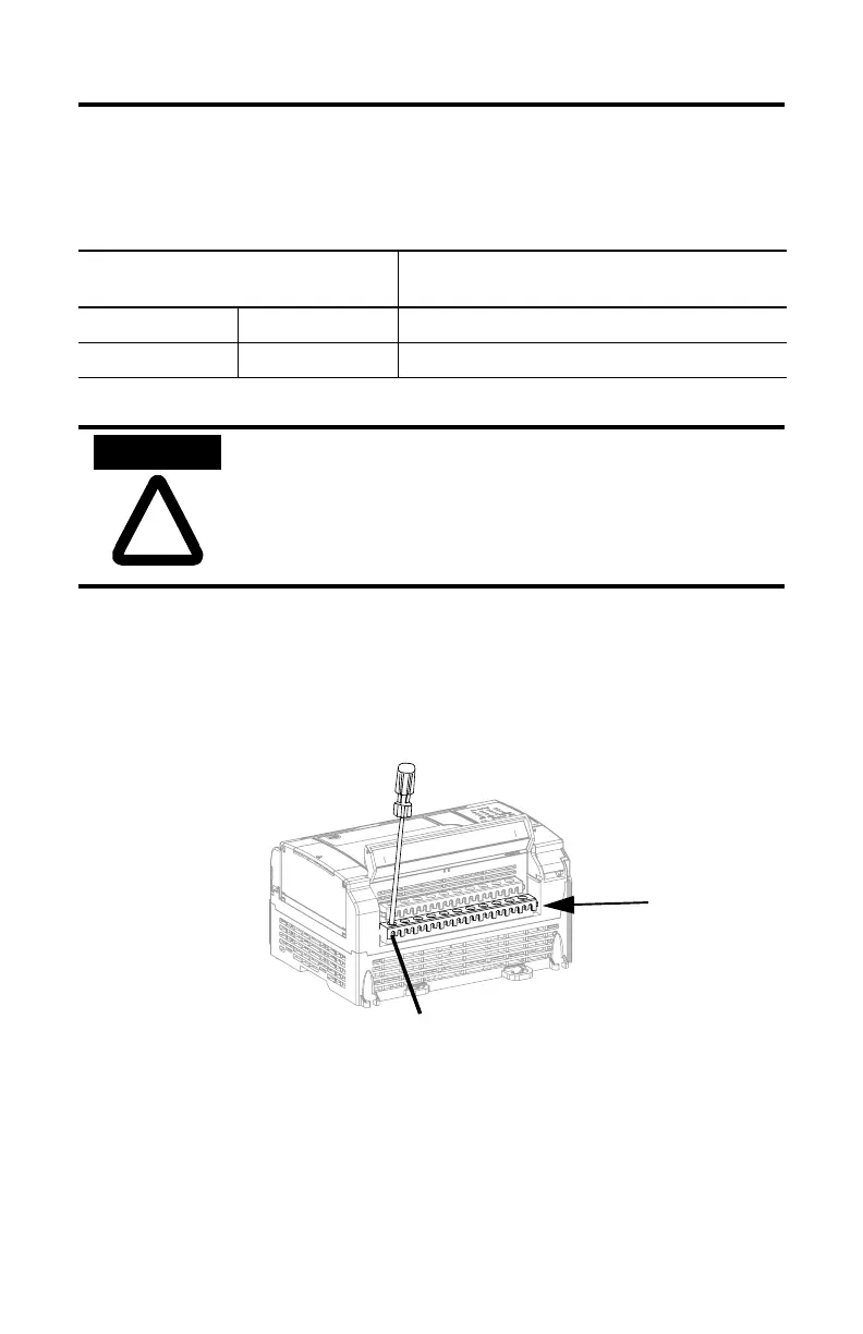
When wiring without spade lugs, keep the finger-safe covers in place. Loosen the
terminal screw and route the wires through the opening in the finger-safe cover.
Tighten the terminal screw making sure the pressure plate secures the wire.
Table 7 Wire Type Recommendation
Wire Type Wire Size (2 wire maximum per terminal
screw)
Solid Cu-90°C (194°F) #14 to #22 AWG
Stranded Cu-90°C (194°F) #14 to #22 AWG
!
ATTENTION
Be careful when stripping wires. Wire fragments that fall into
the controller could cause damage. Once wiring is complete,
be sure the base unit is free of all metal fragments before
removing protective debris strips and installing the processor
unit. Failure to remove strips before operating can cause
overheating.
Finger-Safe Cover
Allen-Bradley Parts

 Loading...


