14 MicroLogix™ 1500 Programmable Controller Base Units
Publication 1764-IN001A-ML-P
Spade Lug Recommendation
The diameter of the terminal screw head is 5.5 mm (0.220 in.). The input and
output terminals of the MicroLogix 1500 base unit are designed for the following
spade lugs. The terminals will accept a 6.35mm (0.25 in.) wide spade (standard
for #6 screw for up to 14AWG) or a 4 mm (metric #4) fork terminal.
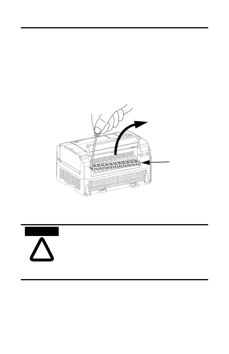
When using spade lugs, use a small, flat-blade screwdriver to pry the finger-safe
cover from the terminal blocks, then loosen the terminal screw.
Surge Suppression
!
ATTENTION
Inductive load devices such as motor starters and solenoids
require the use of some type of surge suppression to protect the
controller output. Switching inductive loads without surge
suppression can significantly reduce the lifetime of relay
contacts or damage transistor outputs. By using suppression,
you also reduce the effects of voltage transients caused by
interrupting the current to that inductive device, and prevent
electrical noise from radiating into system wiring.
Finger-Safe Cover

 Loading...


