92 Unidad Base del Controlador Programable MicroLogix™ 1500
Publication 1764-IN001A-ML-P
Recomendaciones de cableado
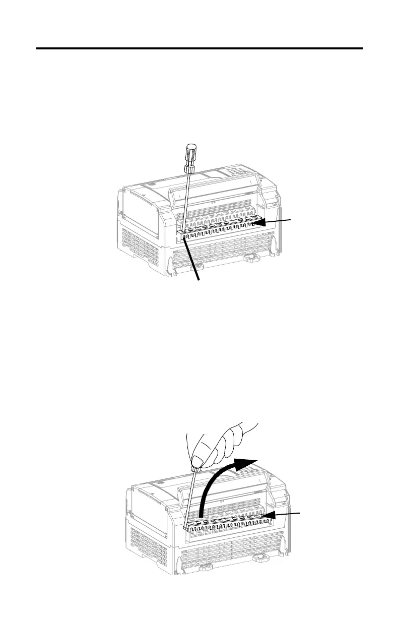
Mantenga la cubierta protectora en su lugar mientras cablea sin terminales. Suelte el
tornillo del terminal y enrute los cables mediante la apertura en la cubierta
protectora. Apriete el tornillo del terminal y asegúrese que los cables estén bien
capturados por la placa de presión.
Recomendaciones para terminales
El diámetro de la cabeza del tornillo es 5,5 mm (0,220 pulg.). Los terminales de
entrada y salida de la unidad base MicroLogix 1500 está diseñados para los siguentes
pernos de pala. Los terminales acceptan una anchura de 6,35mm (0,25 pulg.) (el
estándar para tornillos #6 screw hasta 14 AWG) o un terminal de horqilla de 4 mm
(métrico #4).
Al usar terminales, use un destornillador plano para tratar de abrir la cubierta
protectora del bloque, y entonces puede soltar el tornillo del terminal.
Cubierta protectora
Cubierta protectora

 Loading...


