Do you have a question about the Allen-Bradley PanelView Plus 1250 and is the answer not in the manual?
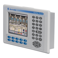
Details the features of PanelView Plus terminals, including display types, touch screen, modularity, and communication ports.
Specifies suitability for hazardous locations (Class I, II, III Divisions) and ignition temperature requirements.
Provides mounting dimensions for PanelView Plus terminals, including depth.
Provides panel cutout dimensions for each PanelView Plus terminal model.
Details the process of installing the terminal in a panel using mounting clips and gasket.
Details the integrated power supply operating on 24V dc and connection procedures.
Explains how to enter Configuration Mode on startup or from a running application.
Guides on loading an RSView ME application and then running it.
Safety precautions before installing/replacing components, including power disconnection and ESD protection.
Shows how to install and replace the Logic Module on the PanelView Plus terminal.
Details how to install and replace a Communication Module on the PanelView Plus terminal.
Shows how to replace the Display Module, requiring removal of Communication and Logic Modules.
Guidelines for wiring and safety, including conduit separation and EMI shielding.
Summarizes PanelView Plus terminal connections to controllers and network interface modules.
Describes the multi-purpose serial RS-232 port and its pinout for controller connections.
Details the Ethernet port, its capabilities, and connector pinout.
Provides general troubleshooting steps, including checking power and logic module LEDs.
Lists system error messages that may display on startup and their descriptions.
Describes error messages for incorrect or invalid components used with the terminal.
| Brand | Allen-Bradley |
|---|---|
| Model | PanelView Plus 1250 |
| Category | Touch terminals |
| Language | English |