PanelView Plus 7 Standard Terminals Mounting Levers 3
Rockwell Automation Publication 2711P-IN032A-EN-P - July 2014
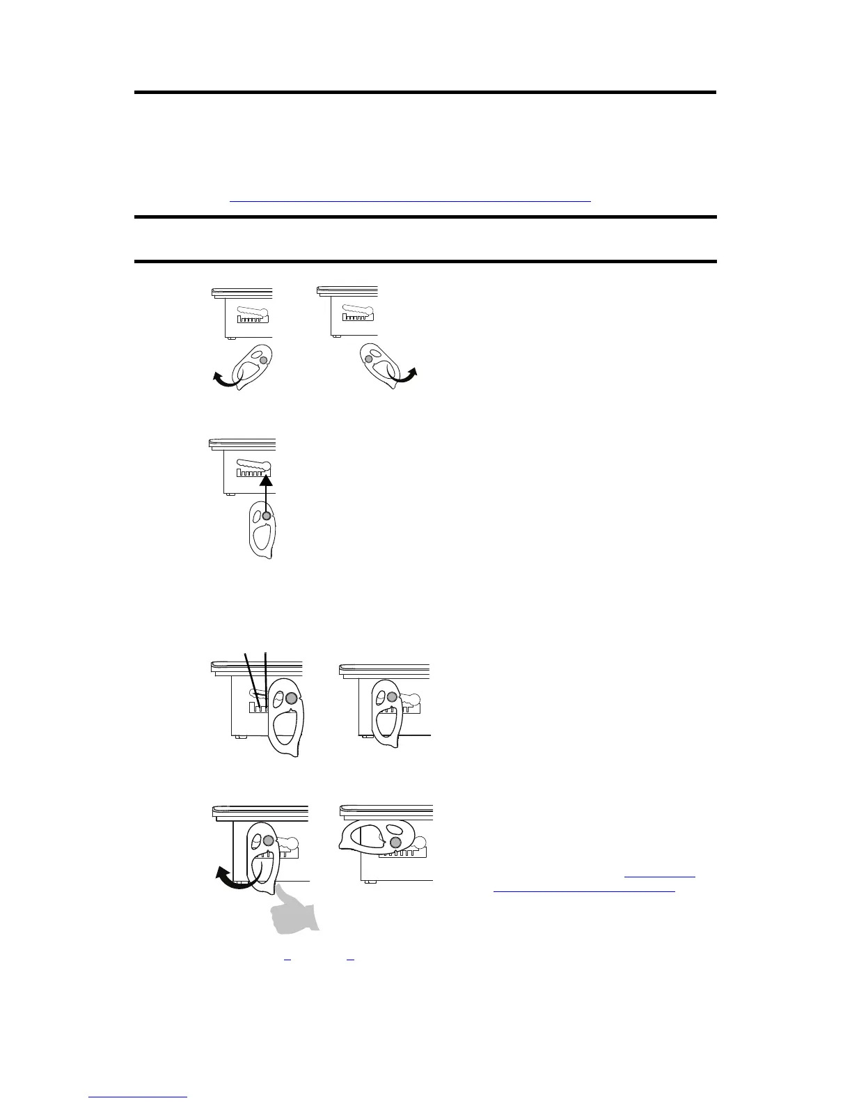
4. Secure the terminal in the panel.
a. Verify the orientation of the mounting levers.
The direction that you rotate each mounting lever is different for each terminal size.
See Mounting Lever Orientation and Lock Sequence
on page 2.
b. Hold the first mounting lever in the locking sequence vertical to the slot and insert
its knob into the large end of the slot.
c. Slide the mounting lever to a notch that is one or two positions greater than the final
locking position for your panel thickness.
If the final locking position is 1, slide the mounting lever to position 2 or 3.
d. Rotate the mounting lever until its flat side comes in contact with the panel.
e. Repeat steps a
through d for the remaining mounting levers.
Use catalog number 2711P-RMCS mounting levers for PanelView Plus 7 standard terminals. Do
not use these mounting levers with any other PanelView Plus terminals.
The mounting levers for PanelView Plus 7 standard
terminals are gray, similar to the color of the bezel.
Do not use black mounting levers; they are not
compatible with PanelView Plus 7 standard terminals.
1
Use an erasable marker or grease pencil to mark
the alignment marks for visibility of the slot
positions and to mark the final lock position.
1
6
The mounting levers are designed to break off the
pin if they are over torqued. This helps to prevent
damage to the bezel. If a pin is broken, turn the
mounting lever around and use the other pin to
continue the installation. See Mounting Lever
Orientation and Lock Sequence on page 2 for
restrictions.

 Loading...


