2 PanelView Plus 7 Standard Terminals Mounting Levers
Rockwell Automation Publication 2711P-IN032A-EN-P - July 2014
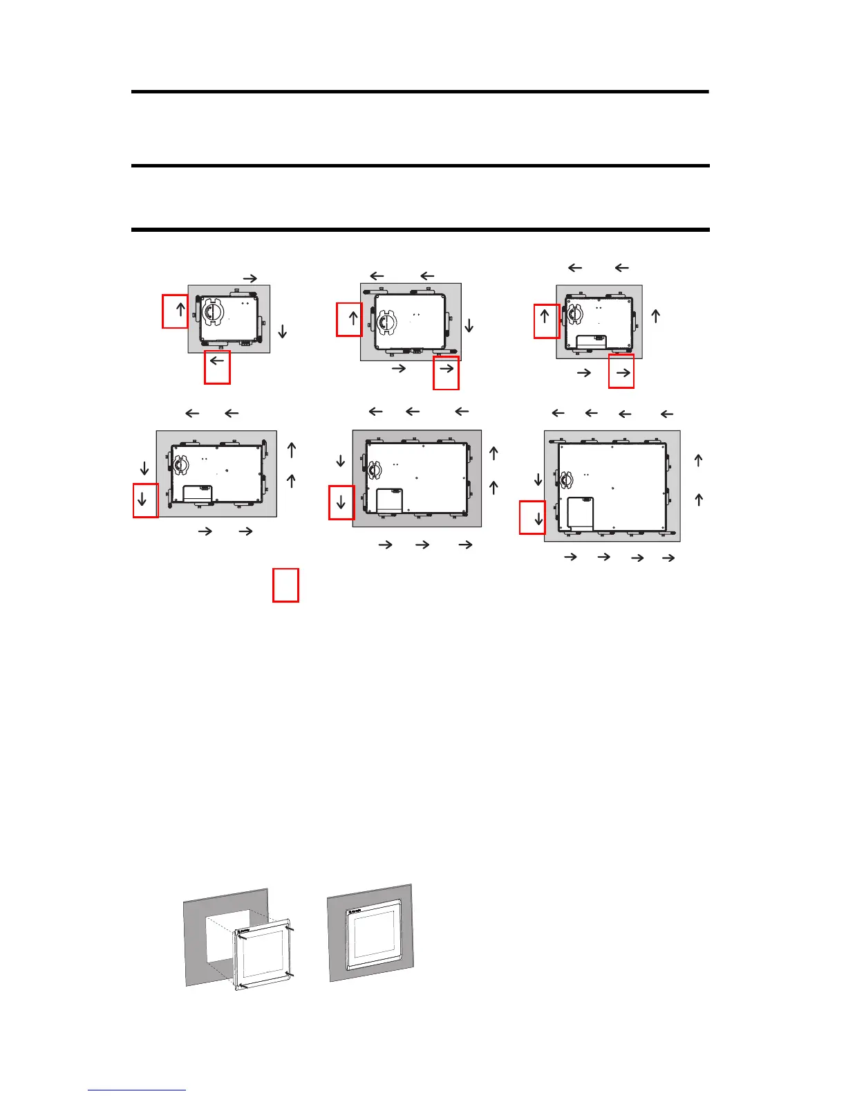
Mounting Lever Orientation and Lock Sequence
Mount the Terminal in a Panel
Follow these steps to mount the terminal in a panel cutout.
1. Use the cutout template that is shipped with your terminal to mark the cutout
dimensions and cut the hole in the panel.
2. Verify the sealing gasket is present on the terminal.
This gasket forms a compression type seal. Do not use sealing compounds.
3. Center the terminal in the panel cutout.
The mounting lever orientations that are shown are required to maintain NEMA, UL Type, and
IP seals. If you require a NEMA, UL Type, or IP seal, do not use a mounting lever in a different
orientation than shown.
8
6
7
5
942
10 13
10.4- and 12.1-in.
24
31
8
6
5
7
9-in.
31
24
6
5
6.5-in.
4.3 in.
3
1
4
2
5.7 in.
6
5
1
3
4
2
6482
7153
9
11
12
10
15-in.
The box indicates that the mounting levers must be
rotated in the orientation that is shown to avoid
interference with ports and cables.

 Loading...