Installation Instructions
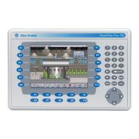
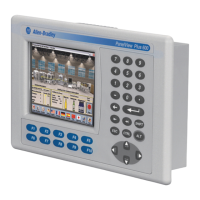
PanelView Plus 7 Standard Terminals
Mounting Levers
Catalog Number
2711P-RMCS
Prepare for Panel Mounting
Mounting levers insert into the slots around the bezel to secure the terminal in the panel. The
number of mounting levers varies by terminal size. Each slot has six notches with alignment
marks that are locking positions for a mounting lever. The thickness of the panel in which you
mount the terminal determines the locking position that is required to maintain NEMA, UL
Type, and IP seals.
Mounting Lever Lock Position
ATTENTION:
• Disconnect all electrical power from the panel before making the panel cutout.
• Make sure the area around the panel cutout is clear and that the panel is clean of any debris,
oil, or other chemicals.
• Make sure that metal cuttings do not enter any components that are already installed in the
panel and that the edges of the cutout have no burrs or sharp edges.
• Failure to follow these warnings can result in personal injury or damage to panel components.
See the PanelView™ Plus 7 Standard Terminals User Manual, publication 2711P-UM007, for
complete installation instructions.
Mounting Slot Mounting Lever
Lock Position
Panel Thickness Range Typical
Gauge
1 1.50…2.01 mm (0.060…0.079 in.) 16
2 2.03…2.64 mm (0.080…0.104 in.) 14
3 2.67…3.15 mm (0.105…0.124 in.) 12
4 3.17…3.66 mm (0.125…0.144 in.) 10
5 3.68…4.16 mm (0.145…0.164 in.) 8/9
6 4.19…4.80 mm (0.165…0.188 in.) 7