236 Rockwell Automation Publication 750-IN001O-EN-P - October 2014
Chapter 5 I/O Wiring
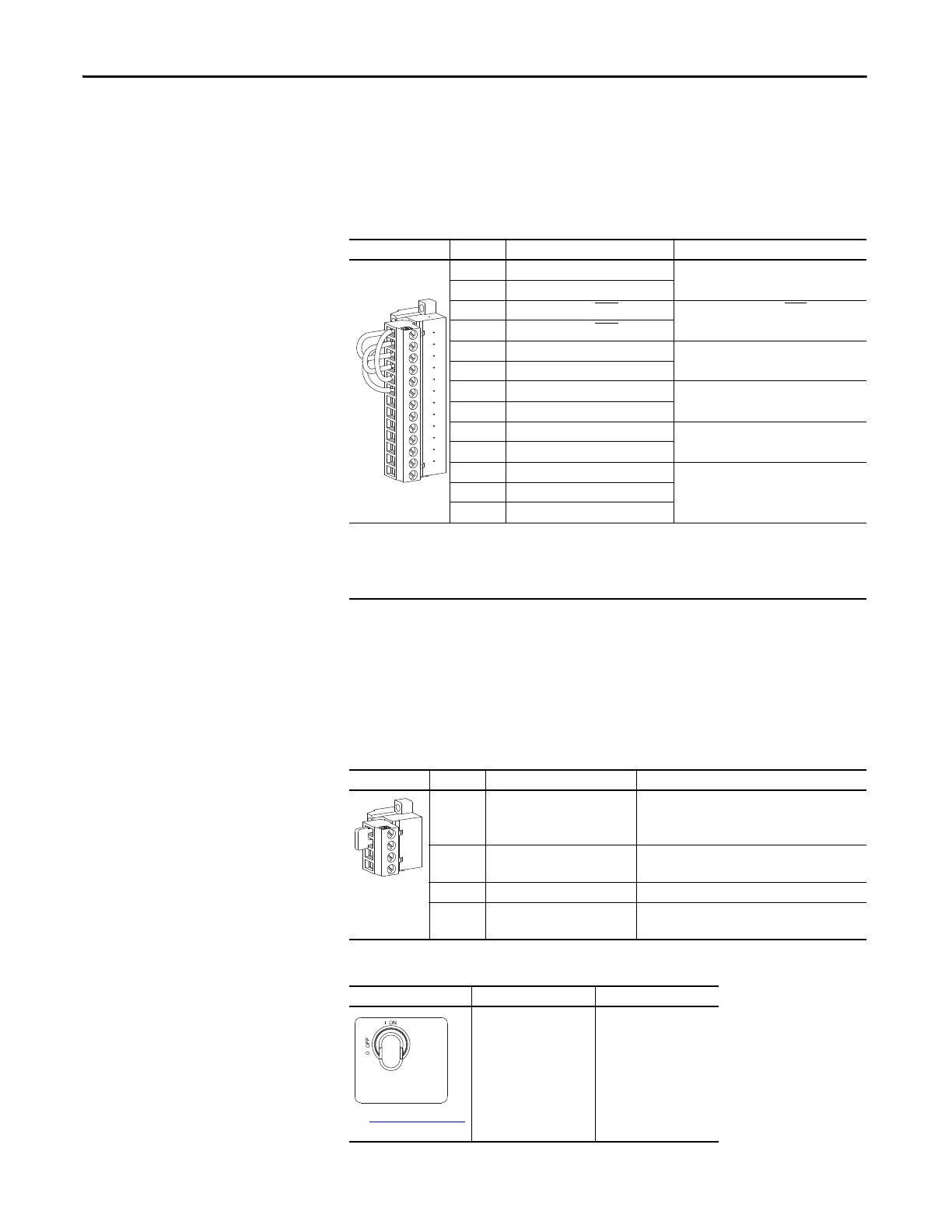
DC Precharge Board
The DC precharge board provides sensing of bus voltage, monitoring of bus fuses
and control over all precharge hardware.
Table 50 - TB3 Terminal Designations
Cabinet Door Interlock and Door Switch
The Common DC Input drive supports the installation of a door interlock
solenoid and door switch.
Table 51 - TB4 Terminal Designations
Disconnect Switch (SW2) Operation
Fixed I/O Terminal Name Description
1 I/O 24V Drive supplied 24V DC I/O power.
2 I/O 24V COMMON
3 EXT. PRCHRG CLOSE/OPEN
INPUT+ External precharge close/open input.
4 EXT. PRCHRG CLOSE/OPEN INPUT-
5 EXT. PRCHRG INHIBIT INPUT+ External precharge inhibit input.
6 EXT. PRCHRG INHIBIT INPUT-
7 RESET FAULTS INPUT + Reset faults input.
8 RESET FAULTS INPUT -
9 PRECHARGE COMPLETE NO Precharge complete normally open input
10 PRECHARGE COMPLETE COM
11 FAULT OUT NC Normally closed contact output.
Normally open contact output.
12 FAULT OUT NO
13 FAULT OUT COM
Factory Jumper Settings:
• TB3-1 and TB3-3
• TB3-1 and TB3-5
• TB3-2 and TB3-4
• TB3-2 and TB3-6
IMPORTANT: Do not remove the factory installed jumpers.
Fixed I/O Terminal Name Description
1 DOOR SWITCH CLOSED Normally open door switch.
Door switch input connection.
Remove TB4-1 to TB4-2 jumper to wire switch.
2 I/O 24V Drive supplied 24V DC power.
Door switch supply or power connection.
3 240 VAC NEUTRAL Solenoid neutral connection.
4 240 VAC HOT DOOR INTERLOCK
SOLENOID
Drive supplied 240V AC power.
Solenoid hot connection.
SW2 is On Door Closed Door Open
See Figure 33 - on page 71
for location.
Solenoid and door switch
circuits are energized.
Alarm is indicated.
1
2
3
4
5
6
7
8
9
10
11
12
13
 Loading...


