18 Rockwell Automation Publication 20HIM-UM001D-EN-P - February 2013
Chapter 2 Installing the HIM
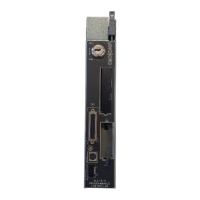
Installing the 20-HIM-C6S
HIM
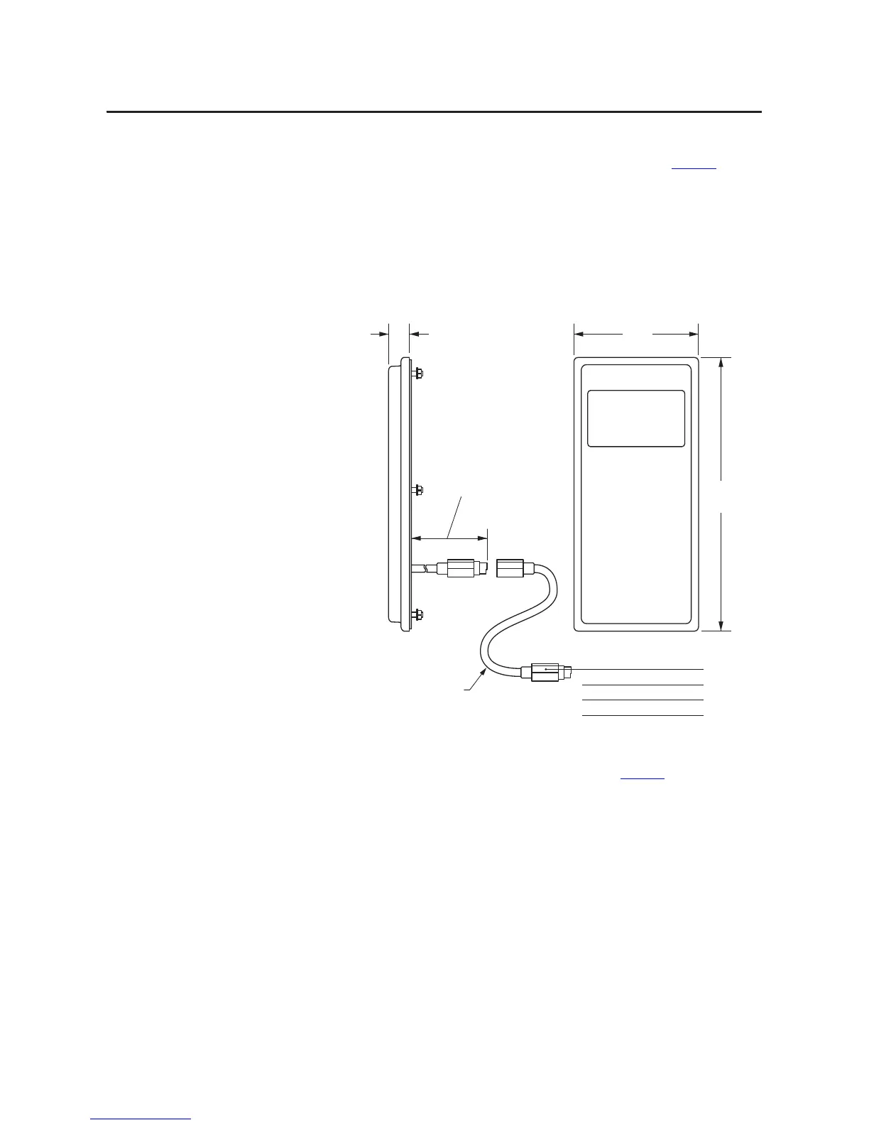
The 20-HIM-C6S (NEMA Type 4X/12) HIM is designed for remote
installation and includes a 3 m/9.8 ft. long 1202-C30 cable. See Figure 1
for
overall HIM dimensions. Choose an appropriate location to mount the 20-HIM-
C6S HIM. The distance between the HIM and drive can be increased up to 75
m/246 ft. by using a 1202-Hxx extension cable or 1202-CBL-KIT-100M cable
kit. However, a cable distance greater than 30 m/98.4 ft. is not CE compliant.
Figure 1 - 20-HIM-C6S HIM Dimensions
1. Drill the required hole pattern in the panel. See Figure 2 for dimensions.
A conversion template (part number 336745-C01), provided with the
20-HIM-C6S HIM, includes a drilling pattern and mounting
instructions to assist with HIM installation.
MFTLONG
#CABLE
INCLUDEDWITH
()-#3()-
(MFTLONG
(MFTLONG
(MFTLONG
(XX%XTENSION#ABLE
SUPPLIEDSEPARATELYANDONLY
NEEDEDIFREQUIREDDISTANCE
EXCEEDS##ABLELENGTH
Dimensions are in millimeters and (inches).
 Loading...