EasyManuals Logo

Allen-Bradley PowerFlex 525 Application Technique

Allen-Bradley PowerFlex 525
24 pages
To Next Page IconTo Next Page
To Previous Page IconTo Previous Page
Page #12 background imageLoading...
Page #12 background image
12 Rockwell Automation Publication SAFETY-AT140A-EN-P - May 2015
Safety Function: Actuator Subsystems – Stop Category 1 via the PowerFlex 525 and PowerFlex 527 Drives with Safe Torque-off
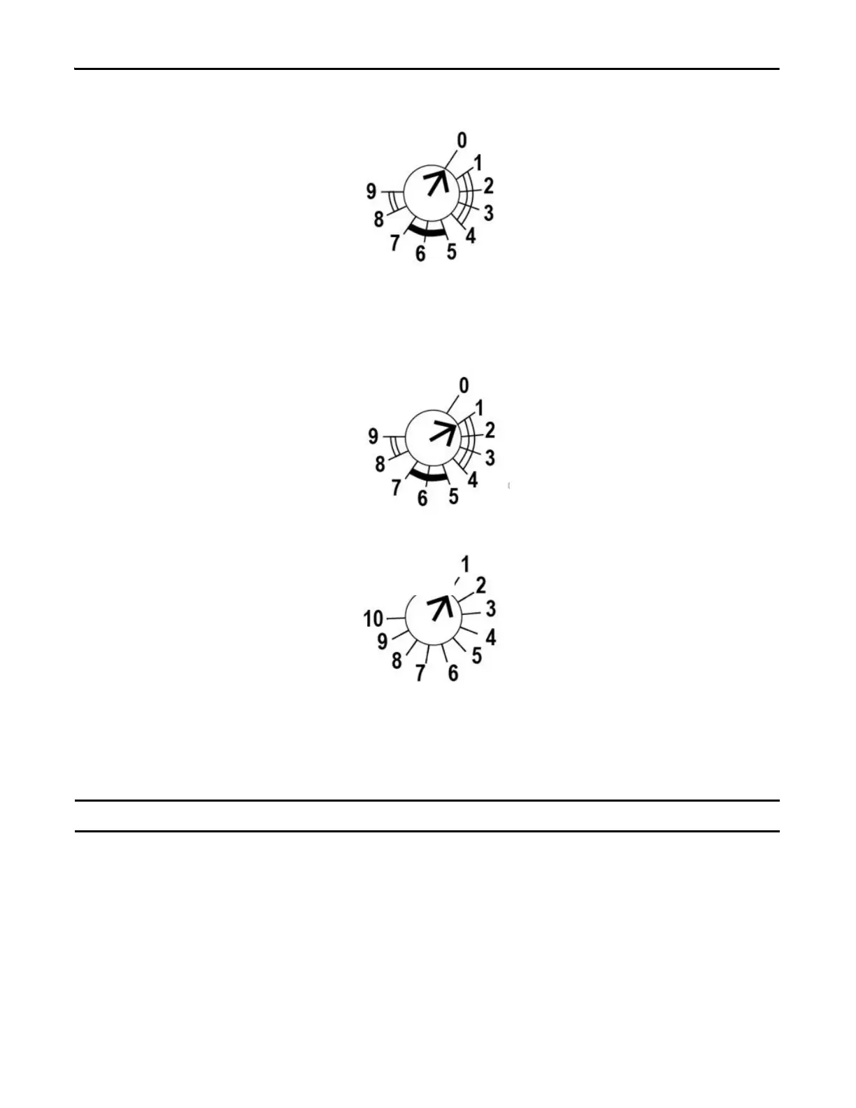
1. Start configuration/overwrite: With power off, turn the Range rotary switch to 0 and power up the unit.
After the power-up test, the PWR/Fault status indicator will flash red.
2. Set timing/mode configuration: Turn the Range rotary switch to 1 (0.1. to 1.0 second), and then turn the Time
rotary switch to 1 (10%).
The B1 and IN indicators blink the new setting. The PWR/Fault status indicator flashes steady green to indicate
that the positions are set.
3. Cycle power to the unit to store the configuration setting.
IMPORTANT
The configuration must be confirmed before operation. A white space is provided on the face of the unit to record the setting.
Range
Range
Time

Other manuals for Allen-Bradley PowerFlex 525

Questions and Answers:

Question and Answer IconNeed help?

Do you have a question about the Allen-Bradley PowerFlex 525 and is the answer not in the manual?

Allen-Bradley PowerFlex 525 Specifications

General IconGeneral
Horsepower0.5-30 HP
kW0.4-22 kW
Input Voltage200-240V AC, 380-480V AC
EnclosureIP20, NEMA/UL Type 1
CommunicationsEtherNet/IP
Control MethodsV/Hz, Sensorless Vector
STOSafe Torque Off (STO)
Output Voltage0-Input Voltage
Operating Temperature-20°C to 50°C (-4°F to 122°F)
Storage Temperature-40°C to 85°C (-40°F to 185°F)
Relative Humidity5-95% non-condensing
DimensionsVaries by model
WeightVaries by model

Related product manuals