Rockwell Automation Publication SAFETY-AT140A-EN-P - May 2015 21
Safety Function: Actuator Subsystems – Stop Category 1 via the PowerFlex 525 and PowerFlex 527 Drives with Safe Torque-off
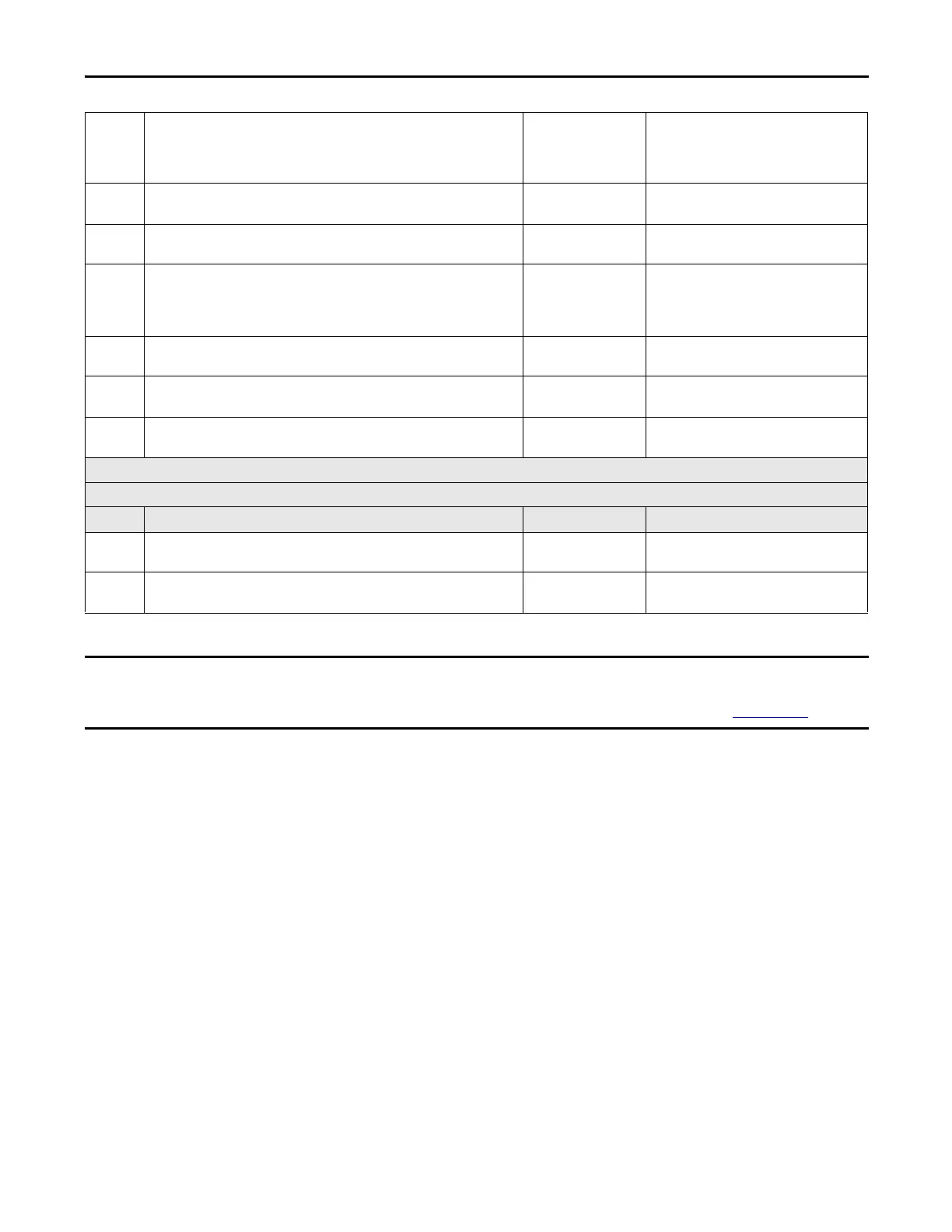
5 Close the gate. Press and release the Reset button. The Guardmaster dual-input safety
relay and the Guardmaster multifunction-delay expansion module reset. The
PowerFlex drive does not respond to the Start button. The PowerFlex drive’s STO fault
remains.
6 Remove the jumper. Press the drive Start button. The drive must not respond. The STO
fault remains.
7 Cycle power to the drive. The STO fault is cleared. Press the Start button. The hazardous
motion starts.
8 While the hazardous motion continues to run, jump 0V to terminal S1 of the
PowerFlex drive. The hazardous motion coasts to a stop. The Guardmaster dual-input
safety relay and the Guardmaster multifunction-delay expansion module are not
affected. The PowerFlex drive has an STO fault.
9 Remove the jumper. Press the drive Start button. The drive must not respond. The STO
fault remains.
10 Cycle power to the drive. The STO fault is cleared. Press the Start button. The hazardous
motion starts.
11 Repeat steps 1 through 10 using the PowerFlex drive’s terminal S2 in place of terminal
S1. The system responses must be the same as before.
Confirmation of Performance - The overall system stopping performance does not exceed 476 ms.
SensaGuard Switch, Guardmaster Dual-input Safety Relay, Guardmaster Multifunction-delay Expansion Module, PowerFlex Drive Tests
Test Step Confirmation Pass/Fail Changes/Modifications
1 Confirm that everything runs safely in the configuration determined to yield the
maximum overall system stopping performance.
2 While the machine continues to run, open the guarded gate. Do not reach into the
guarded area. Confirm that the hazard stops within 476 ms.
In addition to the verification and validation steps provided here, consult the application technique for your input subsystem for
the steps required to validate the input device. For the input subsystem example used in this safety function application
technique, we reference Safety Function: Door Monitoring Products: SensaGuard™ / GSR DI, publication SAFETY-AT069
.

 Loading...


