14 Rockwell Automation Publication SAFETY-AT140A-EN-P - May 2015
Safety Function: Actuator Subsystems – Stop Category 1 via the PowerFlex 525 and PowerFlex 527 Drives with Safe Torque-off
The functional safety data for the SensaGuard switch, Guardmaster dual-input safety relay, Guardmaster multifunction-
delay expansion module, and PowerFlex 525 drive is provided from the Rockwell Automation® SISTEMA library. The
functional safety data for the PowerFlex 527 drive is from the PowerFlex 527 Adjustable Frequency AC Drive User Manual,
publication 520-UM002
.
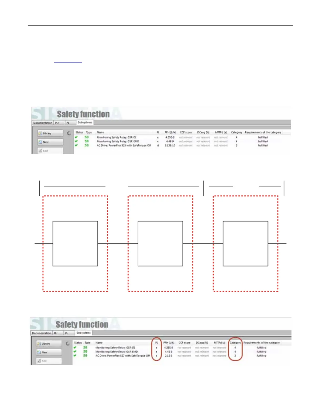
Logic and Output Subsystems Calculation
The PowerFlex 525 drive yields the following results.
This can be modeled as follows:
The PowerFlex 527 drive yields virtually the same results. The same parts produce the same results.
Logic
Output
Subsystem 1
Subsystem 2
Subsystem 3
Guardmaster
Dual-input
Safety Relay
Guardmaster
Multifunction-delay
Expansion Module
PowerFlex
525 Drive

 Loading...


