Rockwell Automation Publication SAFETY-AT140A-EN-P - May 2015 9
Safety Function: Actuator Subsystems – Stop Category 1 via the PowerFlex 525 and PowerFlex 527 Drives with Safe Torque-off
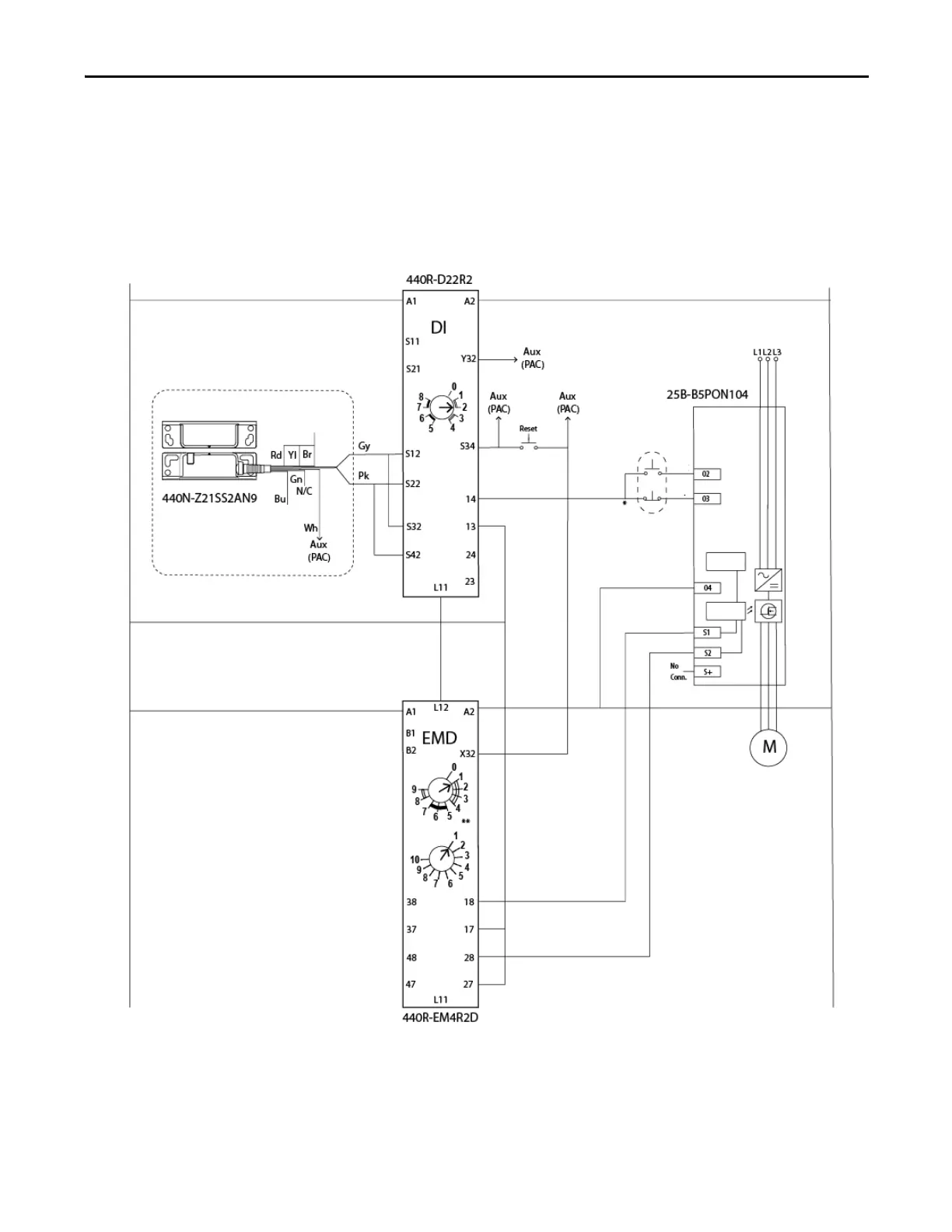
Electrical Schematic
In this application example, a local Start/Stop button is directly wired to the PowerFlex 525 drive. This button is used for
normal, non-safety stops and starts of the system. It is also used to start/restart the drive after safety-related stops once the
safety circuit is reset.
Figure 1 - PowerFlex 525 Circuit
24V DC
0V DC - COM
Typical Safety Input Device
24V DC
0V DC
Start
Stop
Gate control
power supply
Gate control
circuit
Initiate Configured ‘Normal’
Production Stop.
Digital Common
Actuator
Logic
Range
Time
**100 ms OFF Delay
PowerFlex
525

 Loading...


