Sleep Mode 2-165
Sleep/Wake Sources
All defined analog inputs for a product shall be considered as valid Sleep/
Wake sources. The Sleep/Wake function is completely independent of any
other functions that are also using the assigned analog input. Thus, using the
same analog input for both speed reference and wake control is permitted.
Also, [Analog In x Hi] and [Analog In x Lo] parameters have no affect on
the function. However, the factory calibrated result will be used. In addition,
the absolute value of the calibrated result will be used, thus making the
function useful for bipolar direction applications. The analog in loss
function is unaffected and therefore operational with the Sleep/Wake
function, but not tied to the sleep or wake levels.
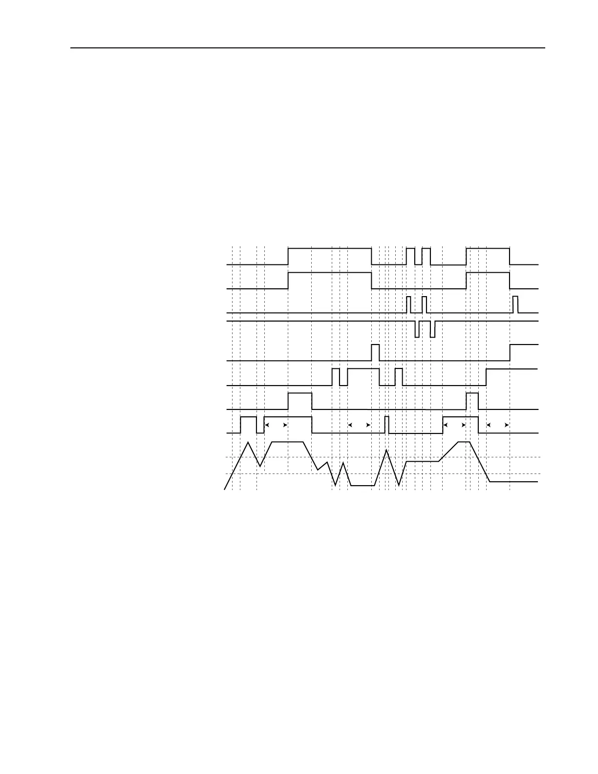
Figure 2.31 Sleep/Wake Function
Drive
Run
Wake Up
Wake
Time
Example Conditions
Wake Time = 3 Seconds
Sleep Time = 3 Seconds
Wake Level
Sleep Level
Analog Signal
Go to Sleep
Sleep-Wake
Function
Start
Stop
Sleep Timer
Satisfied
Wake Timer
Satisfied
Wake Level
Satisfied
Sleep Level
Satisfied
Sleep
Time
Wake
Time
Sleep
Time

 Loading...


