2-184 Start-Up
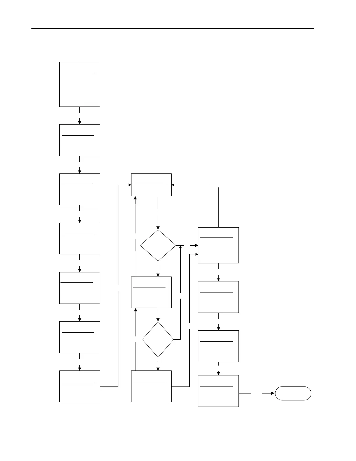
Figure 2.39 PowerFlex 70 & 700 Standard Control Option Startup (2)
StartUp
2. Motr Dat/Ramp
Enter value for
Motor NP Power
123.4 kW
xxx.x <> yyy.y
StartUp
2. Motr Dat/Ramp
Enter value for
Motor NP Volts
123.4 Volt
xxx.x <> yyy.y
StartUp
2. Motr Dat/Ramp
Enter value for
Motor NP FLA
+456.78 Amps
xxx.xx <> yyy.yy
StartUp
2. Motr Dat/Ramp
Enter value for
Motor NP RPM
+456 RPM
xxx <> yyy
StartUp
2. Motr Dat/Ramp
Enter value for
Motor NP Hertz
60.0 Hz
x.x <> y.y
StartUp
2. Motr Dat/Ramp
Enter choice for
Mtr NP Pwr Units
Go to 0-1 (3)
StartUp
2. Motr Dat/Ramp
Enter value for
Accel Time 1
6.0 Secs
0.0 < 60.0 secs
StartUp
2. Motr Dat/Ramp
Enter value for
Decel Time 1
6.0 Secs
0.0 < 60.0 secs
StartUp
2. Motr Dat/Ramp
Enter value for
S Curve %
0 %
0 < 100 %
StartUp
2. Motr Dat/Ramp
Use motor name-
plate data and
required ramp
times for the
following steps.
Basic Start Up (Motor Data/Ramp)
2-0
Enter
2-1
2-2
Enter
Enter
2-3
Enter
2-4
Enter
2-5
2-6
Enter
2-11
Enter
2-12
2-13
Enter
Enter
StartUp
2. Motr Dat/Ramp
Enter choice for
Stop Mode A
2-7
Enter
Enter
StartUp
2. Motr Dat/Ramp
Enter value for
DC Brake Level
1.0 Amps
0.0 < 30.0 Amps
2-8
Yes
StartUp
2. Motr Dat/Ramp
Enter value for
DC BrakeTime
1.0 Secs
0.0 < 90.0 Secs
2-9
Enter
No
StartUp
2. Motr Dat/Ramp
Enter choice for
DB Resistor Type
None
Internal
External
2-10
Enter
Enter
Backup
Backup
None - Bus Reg Mode A = Adj Freq.
Intenal - Bus Reg Mode A = Both, DB 1st.
External - Bus Reg Mode A = Both, DB 1st.
Yes
No
Backup
Stop Mode A
= "DC Brake" or
"Ramp to
Hold"?
Stop Mode A
= "DC
Brake"?

 Loading...


