Evaluating the Internal Resistor 3-3
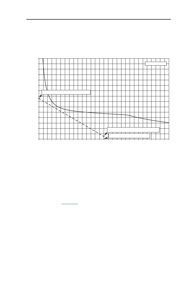
If the line connecting AL and PL lies entirely to the left of the Power
Curve, then the capability of the internal resistor is sufficient for the
proposed application.
Figure 3.1 Example of an Acceptable Resistor Power Curve
If any portion of the line connecting AL and PL lies to the right of the
Power Curve, then the capability of the internal resistor is insufficient
for the proposed application.
• Increase deceleration time (t
3
– t
2
) until the line connecting AL and PL
lies entirely to the left of the Power Curve
or
• Go to Section
4 and select an external resistor from the tables
0 1 2 3 4 5 6 7 8 9 101112131415161718192021222324252627282930
Decel Time (Seconds)
% Peak Power
0
200
400
600
800
1000
1200
1400
1600
1800
2000
2200
2400
2600
2800
3000
PL (Peak Percent Load) = 1521%
AL (Average Percent Load) = 100%
Decel Time = 15.0 Seconds
480V Frame C

 Loading...


