EasyManuals Logo

Allen-Bradley powerflex 700 Reference Manual

Allen-Bradley powerflex 700
300 pages
To Next Page IconTo Next Page
To Previous Page IconTo Previous Page
Page #270 background imageLoading...
Page #270 background image
3-6 Evaluating the Internal Resistor
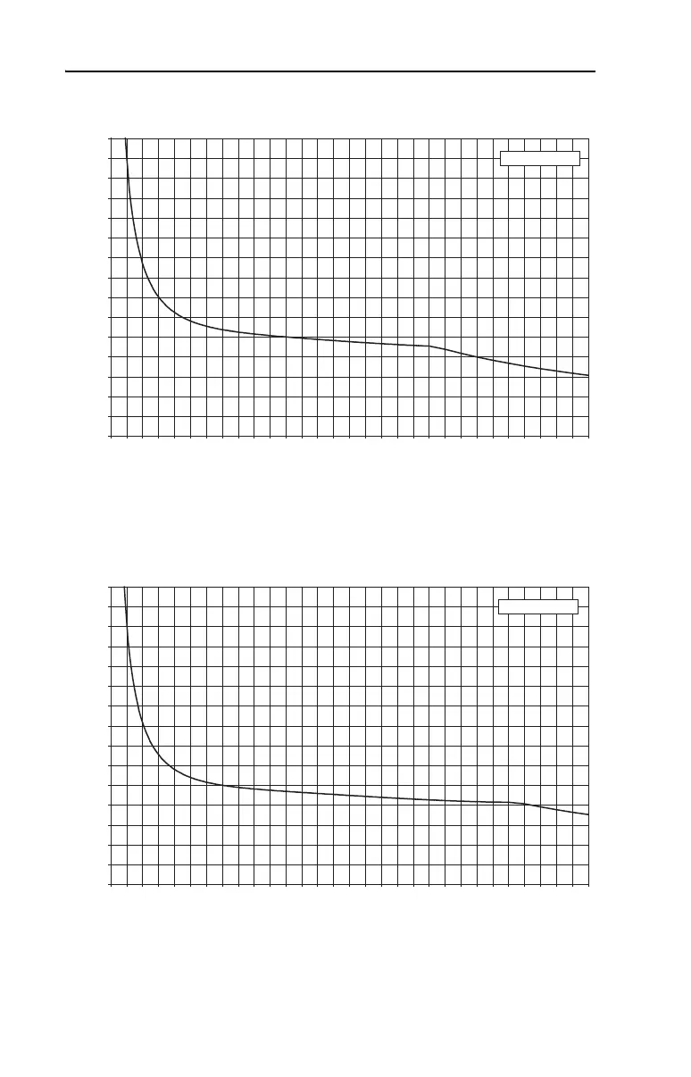
Figure 3.6 PowerFlex 70 – 480 Volt, Frame C
Figure 3.7 PowerFlex 70 – 480 Volt, Frame D
0 1 2 3 4 5 6 7 8 9 101112131415161718192021222324252627282930
Decel Time (Seconds)
% Peak Power
0
200
400
600
800
1000
1200
1400
1600
1800
2000
2200
2400
2600
2800
3000
480V Frame C
0 1 2 3 4 5 6 7 8 9 101112131415161718192021222324252627282930
Decel Time (Seconds)
% Peak Power
0
200
400
600
800
1000
1200
1400
1600
1800
2000
2200
2400
2600
2800
3000
480V Frame D

Table of Contents

Other manuals for Allen-Bradley powerflex 700

Questions and Answers:

Question and Answer IconNeed help?

Do you have a question about the Allen-Bradley powerflex 700 and is the answer not in the manual?

Allen-Bradley powerflex 700 Specifications

General IconGeneral
SeriesPowerFlex 700
CategoryAC Drive
Input Voltage200-240V AC, 380-480V AC, 500-600V AC
EnclosureType 1
Control MethodSensorless Vector
CommunicationEtherNet/IP, ControlNet, DeviceNet, PROFIBUS DP, Modbus

Related product manuals