EasyManuals Logo

Allen-Bradley powerflex 700 Reference Manual

Allen-Bradley powerflex 700
300 pages
To Next Page IconTo Next Page
To Previous Page IconTo Previous Page
Page #276 background imageLoading...
Page #276 background image
4-2 Selecting An External Resistor
Protecting External Resistor Packages
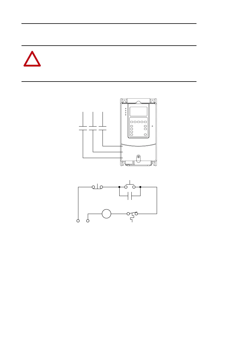
Figure 4.1 External Brake Resistor Circuitry
!
ATTENTION: PowerFlex drives do not offer protection for externally
mounted brake resistors. A risk of fire exists if external braking
resistors are not protected. External resistor packages must be
self-protected from over temperature or the protective circuit show
below, or equivalent, must be supplied.
Power On
R (L1)
S (L2)
T (L3)
Power Source DB Resistor Thermostat
Power Off
M
M
(Input Contactor) M
Three-Phase
AC Input

Table of Contents

Other manuals for Allen-Bradley powerflex 700

Questions and Answers:

Question and Answer IconNeed help?

Do you have a question about the Allen-Bradley powerflex 700 and is the answer not in the manual?

Allen-Bradley powerflex 700 Specifications

General IconGeneral
SeriesPowerFlex 700
CategoryAC Drive
Input Voltage200-240V AC, 380-480V AC, 500-600V AC
EnclosureType 1
Control MethodSensorless Vector
CommunicationEtherNet/IP, ControlNet, DeviceNet, PROFIBUS DP, Modbus

Related product manuals