2-18 Analog Inputs
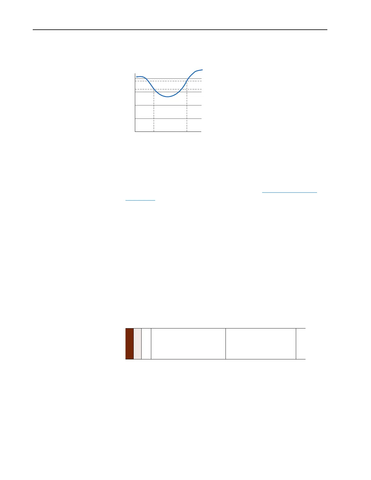
No signal loss detection is possible while an input is in bipolar voltage
mode. The signal loss condition will never occur even if signal loss
detection is enabled.
Trim
An analog input can be used to trim the active speed reference (Speed
Reference A/B). If analog is chosen as a trim input, two scale parameters
are provide to scale the trim reference. The trim is a +/- value which is
summed with the current speed reference. See also Speed Reference
on
page 2-171.
• [Trim In Select]
• [Trim Out Select]
• [Trim Hi]
• [Trim Lo]
Value Display
Parameters are available in the Monitoring Group to view the actual value of
an analog input regardless of its use in the application. Whether it is a
current limit adjustment, speed reference or trim function, the incoming
value can be read via these parameters.
The value displayed includes the input value plus any factory hardware
calibration value, but does not include scaling information programmed by
the user (i.e. [Analog In 1 Hi/Lo]). The units displayed are determined by
the associated configuration bit (Volts or mA)
Cable Selection
Refer to “Wiring and Grounding Guidelines for Pulse Width Modulated
(PWM) AC Drives,” publication DRIVES-IN001 for detailed information
on Cable Selection.
Terminal Designations & Wiring Examples
Refer to the appropriate PowerFlex User Manual or “Wiring and Grounding
Guidelines for Pulse Width Modulated (PWM) AC Drives,” publication
DRIVES-IN001 for I/O terminal designations and wiring examples.
Metering
016
017
[Analog In1 Value]
[Analog In2 Value]
Value of the signal at the analog inputs.
Default:
Min/Max:
Display:
Read Only
0.000/20.000 mA
–/+10.000V
0.001 mA
0.001 Volt
2V
1.9V
1.6V
Signal Loss
Condition
End Signal Loss
Condition

 Loading...


