Rockwell Automation Publication 750-PC100A-EN-P - December 2016
PowerFlex 750-Series Products with TotalFORCE Control 17
Grounding Requirements
The Safety Ground-PE must be connected to system ground. Ground impedance must conform to the
requirements of national and local industrial safety regulations and/or electrical codes. The integrity of all
ground connections should be periodically checked.
Recommended Grounding Scheme
A single point (PE only) grounding scheme should be used. Some applications may require alternate grounding
schemes, refer to Wiring and Grounding Guidelines for Pulse Width Modulated (PWM) AC Drives, publication
DRIVES-IN001
, for more information. These applications include installations with long distances between
drives or drive line-ups, which could cause large potential differences between the drive or line-up grounds.
For installations within a cabinet, a single safety ground point or ground bus bar connected directly to building
steel should be used. All circuits including the AC input ground conductor should be grounded independently
and directly to this point/bar.
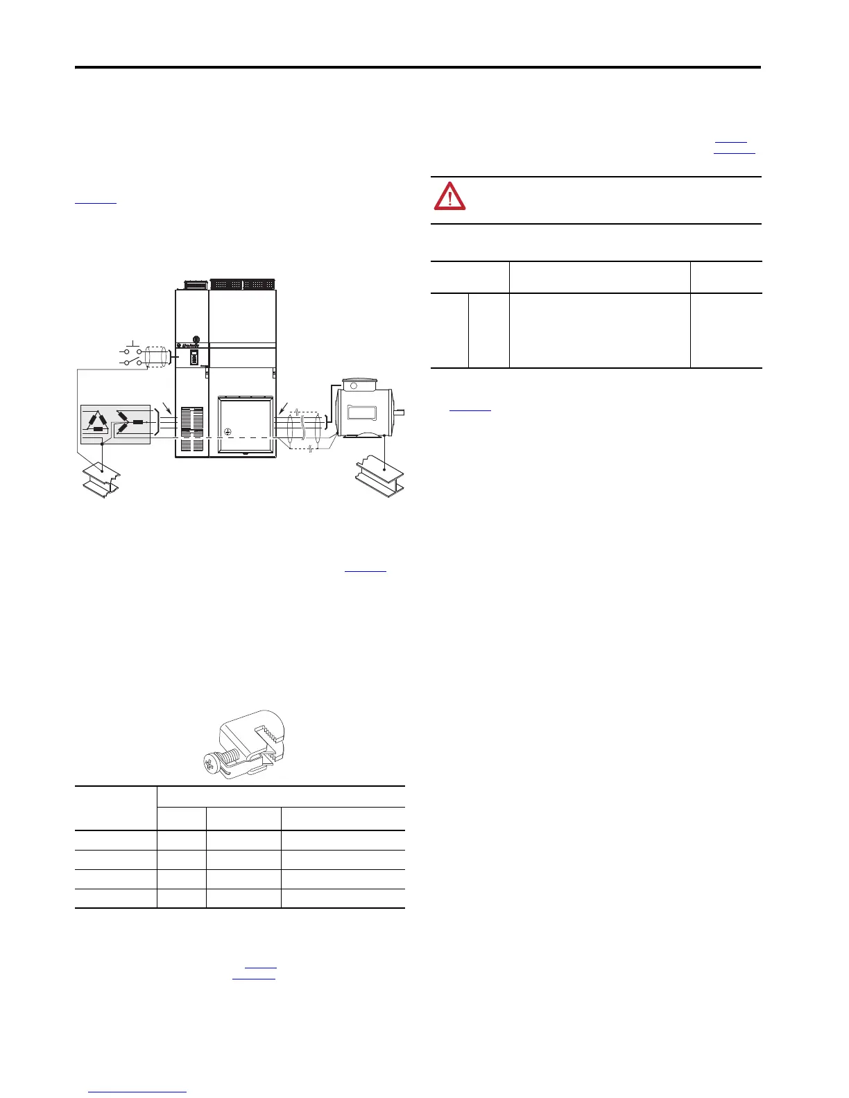
Typical Grounding
Shield Termination - SHLD
The Shield terminal provides a grounding point for the motor cable shield. It must be connected to an earth
ground by a separate continuous lead. Connect the motor cable shield to this terminal on the drive (drive end)
and the motor frame (motor end). Use a shield terminating conduit fitting to connect shield to this terminal. See
Wiring and Grounding Guidelines for Pulse Width Modulated (PWM) AC Drives, publication DRIVES-IN001
.
RFI Filter Grounding
Using an optional RFI filter may result in relatively high ground leakage currents. Therefore, the filter must
only be used in installations with grounded AC supply systems and be permanently installed and
solidly grounded (bonded) to the building power distribution ground. Be sure that the incoming supply
neutral is solidly connected (bonded) to the same building power distribution ground. Grounding must not rely
on flexible cables and should not include any form of plug or socket that would permit inadvertent
disconnection. Some local codes may require redundant ground connections. The integrity of all connections
should be periodically checked. Refer to the instructions supplied with the filter.
Grounding Clamps
The clamp kits listed in this table can be
used to secure round copper ground
conductors to 9.5 mm (0.37 in.) thick
ground bus bars.
The final assembly Safety Ground-PE must be connected to system ground. Ground impedance must conform to
the requirements of national and local industrial safety regulations and/or electrical codes. Periodically check
the integrity of all ground connections. For more information on grounding requirements, see PowerFlex 755TM
IP00/Open Type Kits Installation Instructions, publication 750-IN101
, and Wiring and Grounding Guidelines for
Pulse Width Modulated (PWM) AC Drives, publication DRIVES-IN001
.
Power Wiring
The following section describes the cabling recommendations for three-phase power and motor connections.
For detailed installation instructions including cable entry and exit and customer connections options, refer to
the PowerFlex 750-Series Products with TotalFORCE Control Installation Instructions, publication 750-IN100
. see
also Wiring and Grounding Guidelines for Pulse Width Modulated (PWM) AC Drives, publication DRIVES-IN001
,
for more information on grounding.
Kit Catalog Number Conductor Cross-sections
ISO (mm
2
)
AWG/MCM Tightening Torque N•m (lb•in)
SK-RM-GRNDCLMP-16 2.5…16 14…6 AWG 3 (27)
SK-RM-GRNDCLMP-50 16…50 6…0 AWG 8 (71)
SK-RM-GRNDCLMP-75 35…75 2…00 AWG 12 (106)
SK-RM-GRNDCLMP-185 70…185 00 AWG …350 MCM 15 (133)
U (T1)
V (T2)
W (T3)
R (L1)
S (L2)
T (L3)
SHLD
PE
ATTENTION: National codes and standards (NEC, BSI, and so forth) and local codes outline
provisions for safely installing electrical equipment. Installation must comply with specifications
regarding wire types, conductor sizes, branch circuit protection, and disconnect devices. Failure to
do so can result in personal injury and/or equipment damage.
Cable Recommendations
Type Cable Description Minimum
Insulation Rating
Power
(1)
(2)
(3)
(1) Control and signal wires should be separated from power cables by at least 0.3 meters (1 foot).
(2) The use of shielded cable for AC input power may not be necessary but is always recommended.
(3) See Wiring and Grounding Guidelines for Pulse Width Modulated (PWM) AC Drives, publication
DRIVES-IN001
.
Standard • Three tinned copper conductors with XLPE insulation.
• Maximum 500 MCM conductors.
• Copper braid/aluminum foil combination shield and
tinned copper drain wire, three drain wires per cable
assembly.
•PVC jacket.
600V,
75 °C (167 °F)

 Loading...


