50 Rockwell Automation Publication 750-RM003A-EN-P - April 2018
Chapter 1 Selection Considerations
Device Ports and Main
Control Board I/O
PowerFlex 700AFE Bus Supply
The PowerFlex 700AFE bus supply has limited options to add external
equipment. The PowerFlex 755TM bus supply has many optional I/O and
communication modules.
The PowerFlex 700AFE main control board has fixed I/O module
configurations that you cannot modify. There are a number of cable
connection points that allow various HIM and communication connections.
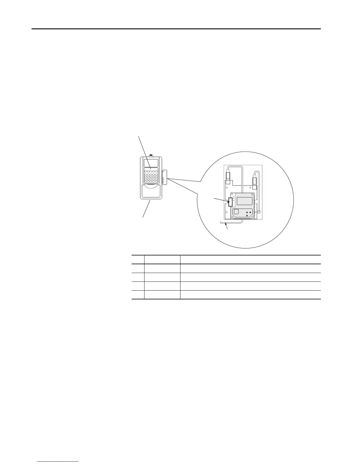
Figure 6 - PowerFlex 700AFE Device Connector Locations
No. Connector
(1)
(1) There is no port 4 on PowerFlex 7-Class products. Port 4 only exists on legacy SCANport™ products.
Description
1 DPI port 1 HIM connection when installed in AFE.
2 DPI port 2 Cable connection for handheld and remote options.
3 DPI port 3 or 2 Splitter cable that is connected to DPI Port 2, which provides an additional port.
4 DPI port 5 Cable connection for communications adapter.
X1
X2
HIM panel opens to allow access to
DPI™ interface. To open the panel,
remove the screws on left side of
the HIM panel and swing open.
To Drive Control
(DPI Interface Board)
1
2, 3
4

 Loading...


