Rockwell Automation Publication PFLEX-IN015A-EN-P - March 2005 3
PowerFlex 700S and 700H Fan Inverter Upgrade Kit (Frame 9)
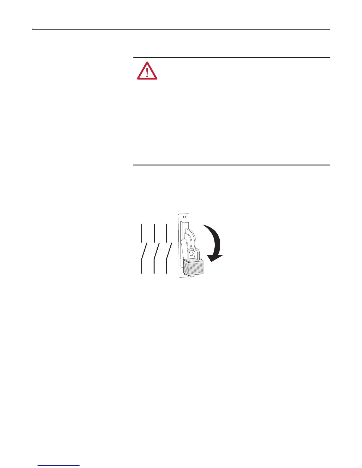
Step 1: Removing Power
from the Drive
1. Turn off and lock out input power. Wait five minutes.
2. Verify that there is no voltage at the drive’s input power terminals.
3. Measure the DC bus voltage at the DC+ & DC- terminals on the Power
Terminal Block. The voltage must be zero.
ATTENTION: To avoid an electric shock hazard, verify that the voltage on the bus
capacitors has discharged before performing any work on the drive. Measure the
DC bus voltage at the DC+ & DC- terminals of the Power Terminal Block. The
voltage must be zero.
ATTENTION: Remove power before making or breaking cable connections.
When you remove or insert a cable connector with power applied, an electrical
arc may occur. An electrical arc can cause personal injury or property damage by:
• sending an erroneous signal to your system’s field devices, causing unintended
machine motion
• causing an explosion in a hazardous environment
Electrical arcing causes excessive wear to contacts on both the module and its
mating connector. Worn contacts may create electrical resistance.

 Loading...


