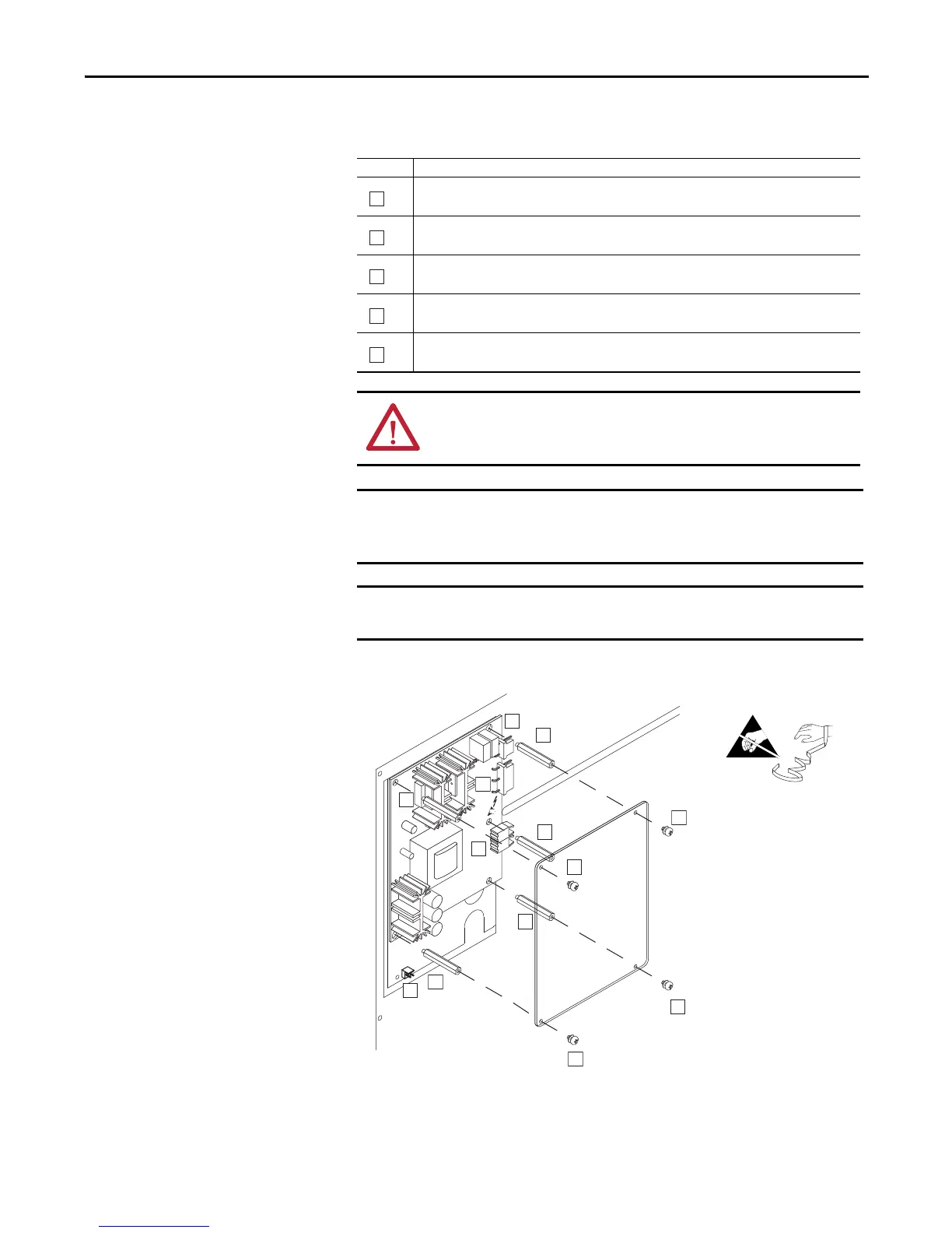
Task Description
Carefully disconnect fiber-optic cables from sockets J4 and J5 of the Voltage Feedback Circuit Board, and carefully set
them aside.
Disconnect cables from sockets J1, J2 and J8.
Remove the four M3x6 Phillips screws, which secure the clear plastic shield to the standoffs, and remove the shield.
Proper tightening torque for reassembly is 0.9 N
•m (8 lb•in).
Remove the five 3 mm hex standoffs, which support the clear plastic shield, and secure the Voltage Feedback Circuit
Board to its mounting plate. Proper tightening torque for reassembly is 0.9 N
•m (8 lb•in).
Remove the Voltage Feedback Circuit Board from its mounting plate.
ATTENTION: Hazard of permanent eye damage exists when using optical
transmission equipment. This product emits intense light and invisible
radiation. Do not look into fiber-optic ports or fiber-optic cable connectors.
Minimum inside bend radius for fiber-optic cable is 25.4 mm (1 in.). Any
bends with a shorter inside radius can permanently damage the fiber-optic
cable. Signal attenuation increases with decreased inside bend radii.
Before removing connections and wires, mark the connections and wires to
avoid incorrect wiring during assembly.

 Loading...


