6 Rockwell Automation Publication PFLEX-IN015A-EN-P - March 2005
PowerFlex 700S and 700H Fan Inverter Upgrade Kit (Frame 9)
700S Control Assembly (on 700S drives only)
On 700S drives, you must also remove the Control Assembly, the Voltage
Feedback Circuit Board and the Power Interface Circuit Board.
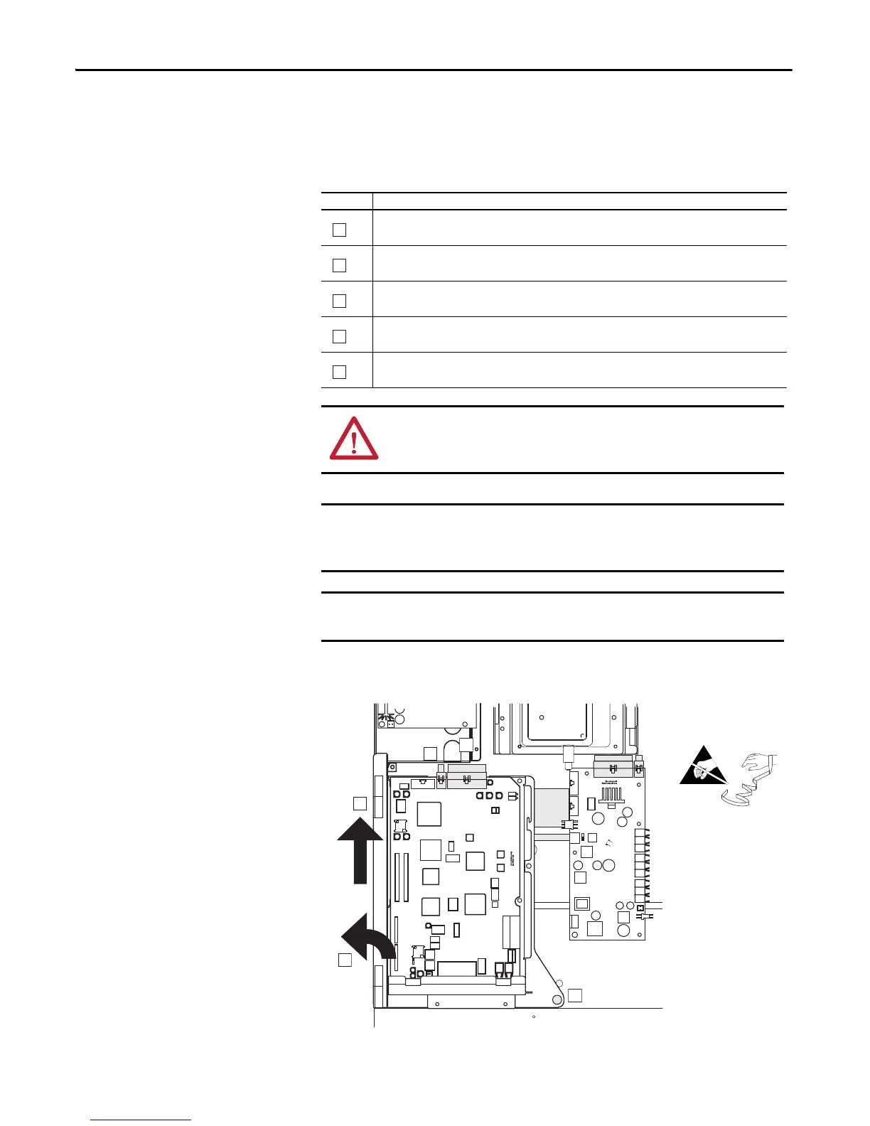
Task Description
On the 700S control assembly, unplug I/O and SynchLink cables from the Main Control Board, unplug
feedback wiring from feedback option card and unplug communication cables from Drivelogix controller.
Unplug the J2 and J7 ribbon cables from the Main Control Board.
Loosen the captive screw.
Swing the Control Assembly towards the front of the drive.
Lift the Control Assembly up and off of the hinge.
ATTENTION: Hazard of permanent eye damage exists when using optical
transmission equipment. This product emits intense light and invisible
radiation. Do not look into fiber-optic ports or fiber-optic cable connectors.
Minimum inside bend radius for fiber-optic cable is 25.4 mm (1 in.). Any
bends with a shorter inside radius can permanently damage the fiber-optic
cable. Signal attenuation increases with decreased inside bend radii.
Before removing connections and wires, mark the connections and wires to
avoid incorrect wiring during assembly.
B
B
C
E

 Loading...


